Hi all,
I'm trying to design a crossover (basically by ear and trial and error) for a 3 way centre, W(MT)W consisting of two Vifa P17WJ-00-08 woofers, one Peerless 830870 Midrange and one Vifa D25AG35-06 tweeter.
I'm using a reference speaker system to help with voicing.
The upper x-over point is no so much an issue, as its more or less just like a conventional vertical 2 way.
However, the lower x-over point is giving me headaches. Basically, I'm trying to achieve the best horizontal tonal consistency as that's important to me in this application.
I've read that this type of 3 way centre is the way to go here, as the lower crossover point can be set low enough to avoid major issues.
It definitely works much better that a 2 way (WTW) one I tried last year with the same drivers. (minus the Peerless midrange)
However, I'm still not happy enough, so I'm trying to see if anyone can possibly help me with this.
A few general questions:
What's the ideal x-over frequency here for my baffle size, driver spacing etc? (I'm guessing around 500Hz or less????)
Is it best to use a 12db/oct or 6/db/oct slope?
Midrange polarity reversed or in phase with woofers?
I realise these may be too general to answer easily and trial and error is the best way to find out, but I'm just trying to gather whether there's a tried and true way of doing this that anyone may know of.
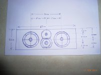
A (dodgy) drawing of the front baffle arrangement is below. 🙂
Speaker drivers datasheets are here:
http://www.madisound.com/store/manuals/p17wj-00-08e.pdf
http://www.essentialaudio.com.au/pdf/peerless/Peerless_830870.pdf
http://www.d-s-t.com.au/data/Vifa/D25AG-35-06.pdf
Any help is appreciated.
Thanks.
I'm trying to design a crossover (basically by ear and trial and error) for a 3 way centre, W(MT)W consisting of two Vifa P17WJ-00-08 woofers, one Peerless 830870 Midrange and one Vifa D25AG35-06 tweeter.
I'm using a reference speaker system to help with voicing.
The upper x-over point is no so much an issue, as its more or less just like a conventional vertical 2 way.
However, the lower x-over point is giving me headaches. Basically, I'm trying to achieve the best horizontal tonal consistency as that's important to me in this application.
I've read that this type of 3 way centre is the way to go here, as the lower crossover point can be set low enough to avoid major issues.
It definitely works much better that a 2 way (WTW) one I tried last year with the same drivers. (minus the Peerless midrange)
However, I'm still not happy enough, so I'm trying to see if anyone can possibly help me with this.
A few general questions:
What's the ideal x-over frequency here for my baffle size, driver spacing etc? (I'm guessing around 500Hz or less????)
Is it best to use a 12db/oct or 6/db/oct slope?
Midrange polarity reversed or in phase with woofers?
I realise these may be too general to answer easily and trial and error is the best way to find out, but I'm just trying to gather whether there's a tried and true way of doing this that anyone may know of.
A (dodgy) drawing of the front baffle arrangement is below. 🙂
Speaker drivers datasheets are here:
http://www.madisound.com/store/manuals/p17wj-00-08e.pdf
http://www.essentialaudio.com.au/pdf/peerless/Peerless_830870.pdf
http://www.d-s-t.com.au/data/Vifa/D25AG-35-06.pdf
Any help is appreciated.
Thanks.
Attachments
Textbook filters will not account for complex impedance curves, and you will likely never be happy in the long run.
A completely custom simulated crossover could be done based on the manufacturers posted measurements and TS parameters. It might not be 100% accurate, depends on how far off the data is, but it is 100 times better then textbook filters.
A completely custom simulated crossover could be done based on the manufacturers posted measurements and TS parameters. It might not be 100% accurate, depends on how far off the data is, but it is 100 times better then textbook filters.
100% agreed, and that's why I'm doing it by trial and error, off the shelf stuff has never worked for me.
I guess I'm just trying to determine if there is a particular slope or x-over freq that may be more suitable for this arrangement. (for horizontal consistency.)
I can do the fine tuning but I'm looking for a general direction, if that makes sense.
If that's not possible, then so be it. 🙁
I guess I'm just trying to determine if there is a particular slope or x-over freq that may be more suitable for this arrangement. (for horizontal consistency.)
I can do the fine tuning but I'm looking for a general direction, if that makes sense.
If that's not possible, then so be it. 🙁
Its going to be extremely hard to cross the woofers over without knowing what is going on, large inductors/caps have a peaking effect.
I have read that the woofers in this arrangement are best used in an angled baffle ( 45 ) and crossed as low as possible This may also work better with the mids and uppers in MTM configuration
Is this for speech or singing? This is an Audax setup by Joe D' Appolito and they crossover at 400 and 3500 Hz, box tuned to 50 Hz.
Last edited:
Really couldn't think about this much without a schematic of your current trial crossover. The volume of the mid enclosure and bass enclosure is relevant too. Is it reflex?
2X 6.5" polycone bass and a 4" polycone mid it seems. Fairly regular sort of tweeter.
Troels has a 3-way design, Mark 21, not a million miles away in drivers and I don't see an issue in rearranging it as D'Appolito:
Mark 2115
Are you somewhere near those values? You really need to explain yourself clearly. This is way too much homework as it stands. 🙂
A few general questions:
What's the ideal x-over frequency here for my baffle size, driver spacing etc? (I'm guessing around 500Hz or less????)
Is it best to use a 12db/oct or 6/db/oct slope?
Midrange polarity reversed or in phase with woofers?
A simulation of the horizontal off-axis response of the woofers helps to answer your questions:

A crossover frequency of 500 Hz is already critical, 300-400 Hz seems to be on the safe side. A 2nd order low-pass filter (12 dB/oct) is inevitable to compensate the rising frequency response caused by the baffle step. The midrange polarity is always reversed to the woofer.
As Jay mentioned, the lower crossover of a 3-way is very tricky, and you have little chance to get it right without simulation or measurements. To make a simulation and propose a crossover, I need some additional information:
- cabinet depth and wall thickness
- sealed or vented, vent dimensions
- volume of the midrange housing
- current crossover (any reusable components?)
- distance and vertical displacement of the listening position (related to the tweeter)
Thanks for the replies so far, .....interesting.
The system above looks to have different values to mine, but not massively different, they could be worth a go.
To try and answer the questions:
Midrange volume is approx 7L sealed.
Each woofer has a separate volume of approx 12L, each with a 5cm dia port 28cm long. (although the port length is not necessarily final yet)
Cabinet depth is 34 cm, all built with 18mm thick MDF.
It is positioned below the TV, so is below ear level. From tweeter level upwards is important.
Horizontally, 45 degrees would be a minimum, even up to 60 would be great if at all possible. But I know that could be pushing it.
I originally had the woofers wired in series as I thought they were too efficient when used in in parallel for the other 2drivers.
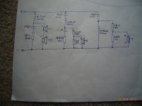
Below is one crossover schematic I used for a while which sounded quite good to my ears.
However since then, I've tried 12db/oct of various combinations, reversed 'mid' and 'tweeter' polarity, and then even went back to parallel but that throws off all the values and sensitivities, so need to start again, so that's when I decided to get on here. 🙂
Hope this helps a bit more, but its sorta hard to explain. 😕
The system above looks to have different values to mine, but not massively different, they could be worth a go.
To try and answer the questions:
Midrange volume is approx 7L sealed.
Each woofer has a separate volume of approx 12L, each with a 5cm dia port 28cm long. (although the port length is not necessarily final yet)
Cabinet depth is 34 cm, all built with 18mm thick MDF.
It is positioned below the TV, so is below ear level. From tweeter level upwards is important.
Horizontally, 45 degrees would be a minimum, even up to 60 would be great if at all possible. But I know that could be pushing it.
I originally had the woofers wired in series as I thought they were too efficient when used in in parallel for the other 2drivers.
Below is one crossover schematic I used for a while which sounded quite good to my ears.
However since then, I've tried 12db/oct of various combinations, reversed 'mid' and 'tweeter' polarity, and then even went back to parallel but that throws off all the values and sensitivities, so need to start again, so that's when I decided to get on here. 🙂
Hope this helps a bit more, but its sorta hard to explain. 😕
Attachments
A crossover proposal using as many as possible of the existing crossover components. The design is optimized for a listening distance of 3 m and a vertical angle of 15 degrees. The simulation attached refers to that position also. The lower crossover frequency is about 430 Hz, couldn't go lower using the 4.7 mH woofer coil and the 47 uF midrange capacitor...


shmb,
Do you already own the drivers?
Yes I do, the system is already up and running, but with an unfinished, external crossover.
A crossover proposal using as many as possible of the existing crossover components. The design is optimized for a listening distance of 3 m and a vertical angle of 15 degrees. The simulation attached refers to that position also. The lower crossover frequency is about 430 Hz, couldn't go lower using the 4.7 mH woofer coil and the 47 uF midrange capacitor...
View attachment 331515
View attachment 331516
I can go larger in the inductor if I have to, I have a Jaycar 9mH (lower quality coil) to put in just for testing.
Same with Cap values. ( I have cheap bi-polar ones for testing)
How much horizontal spread would this design have?
Anyway, its something to try out and see, Thanks heaps for that, I'll give it a go. 🙂
You give Dissi's design a go, my friend. Exactly as stated. He has rescued you. 🙂
You're not going to warm to me when I tell you your own efforts were laughably bad. But it's the truth. 🙄
It's a fairly standard idea to wire the two basses in series for a centre speaker, and it can be a bit woolly on the bass because the damping factor goes to hell, but frankly the SPL levels would never match any other way. 😎
Oh I knew it wasn't right, even though it sounded ok, but I tried various other combos too. Some were better than others in different ways. But no wow factor. 😕
I've had success with standard 2 way designs in the past but this setup was something new to me.
Its hard when you do it by ear too, ......no measuring and no software. 🙁
What exactly was so bad? Freq response? Horizontal response? Phase response? Impedence? .........😱 Everything?
Did you plot a graph with my crossover? If so what did it look like? Dunno if I wan't to see it though. 😱
BTW: I did Dissi's crossover last night and it is, as expected, much improved, especially in the lower crossover region. Maybe just a touch bright in the tweeter, but I can work on that.
Thank you very much.
Now to get this software program. 😀
I did model your rather vague crossover. It seemed to be essentially a two-way crossing over at about 3kHz with a midrange added to do something. Phase matching was non-existent too. 🙂
What the heck is the shunt on the bass doing, for instance? Nothing! 😕
It was obvious that the midrange was not efficient enough to work except with series woofers to keep the SPL down. Dissi's design seems to be doing about the right things although the treble filter is a bit odd.
An externally hosted image should be here but it was not working when we last tested it.
What the heck is the shunt on the bass doing, for instance? Nothing! 😕
It was obvious that the midrange was not efficient enough to work except with series woofers to keep the SPL down. Dissi's design seems to be doing about the right things although the treble filter is a bit odd.
Ok, fair enough. 🙄 Yeah that shut wasn't doing much, I already knew that, it was removed soon after that picture was drawn.
Anyway Dissi's crossover is in use now, and is no doubt much much better.
I just had to pad the tweeter down a bit more, .....after a bit of playing and a few listening tests, all is now good.
Thanks again.🙂
Anyway Dissi's crossover is in use now, and is no doubt much much better.
I just had to pad the tweeter down a bit more, .....after a bit of playing and a few listening tests, all is now good.
Thanks again.🙂
.... and it can be a bit woolly on the bass
because the damping factor goes to hell, ....
Hi,
Care to elaborate on that misinformation ?
rgds, sreten.
Perhaps the man is used to tube amps?Hi,
Care to elaborate on that misinformation ?
rgds, sreten.
- Status
- Not open for further replies.
- Home
- Loudspeakers
- Multi-Way
- 3 way centre speaker crossover. W(MT)W