I recently started designing a center channel speaker using 2 extremis 6.8's, one Renaissance MSD-56 2" soft dome mid, and one Renaissance MST-335 tweeter (similar to Morel MDM-55 and MDT-33, respectively).
~T~
WMW
The following is my crossover design, I am hoping for constructive criticism and corrections if any massive blunders were made (very possible).
Key points:
-Crossover Frequencies:
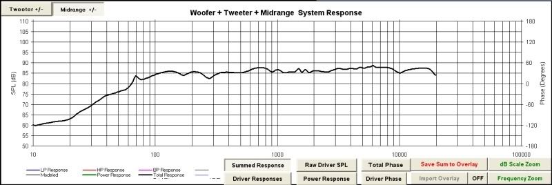
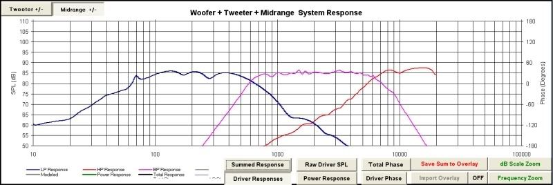
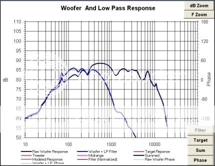
*Woofers taken out at 500Hz via second order Linkwitz-Riley target transfer function, second order parallel electrical. This low xover is due to the hump in frequency they seem to have in that area, so their response seems to stay flat well above the crossover frequency, filling in between 500 and the mid. Will it work like this in reality or will I end up with a hole in the response? Looks good on the graph though.
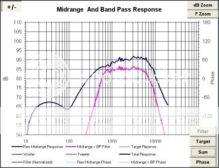
*Midrange bandpass 950Hz to 5500Hz via second order Linkwitz-Riley target, second order electrical filter order on both high and low pass. Reversed polarity wiring.
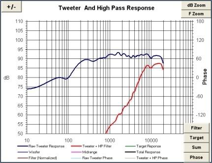
*Tweeter high pass, 5500Hz second order Linkwitz-Riley target, third order parallel electrical filter. Third order due to the tweeter still having output all the way down to 100Hz at a very low level with second. Trying to keep midrange mostly on one driver.
-FRD and ZMA data modeled only, no testing gear. Modeled approximately from manufacturer's spec sheet graphs. No graphs available for mid, so used MDM-55 graph. Not ideal. Anyone have actual graphs for these drivers or better, measured FRD and ZMA files? Is this type of theoretical modeling usually far enough off from reality to make designing mostly pointless? Or close enough?
-Resistors in the right places? Software vague on this.
-Component values will vary at time of purchase. Obviously simulation values.
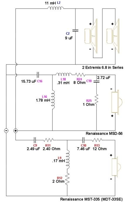
Crossover Component Layout:
Summed System Response:
Filtered Driver Responses:
Raw and Filtered Woofer Comparison:
Raw and Filtered Midrange Comparison:
Raw and Filtered Tweeter Comparison:
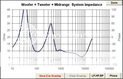
Combined System Impedance:
~T~
WMW
The following is my crossover design, I am hoping for constructive criticism and corrections if any massive blunders were made (very possible).
Key points:
-Crossover Frequencies:
*Woofers taken out at 500Hz via second order Linkwitz-Riley target transfer function, second order parallel electrical. This low xover is due to the hump in frequency they seem to have in that area, so their response seems to stay flat well above the crossover frequency, filling in between 500 and the mid. Will it work like this in reality or will I end up with a hole in the response? Looks good on the graph though.
*Midrange bandpass 950Hz to 5500Hz via second order Linkwitz-Riley target, second order electrical filter order on both high and low pass. Reversed polarity wiring.
*Tweeter high pass, 5500Hz second order Linkwitz-Riley target, third order parallel electrical filter. Third order due to the tweeter still having output all the way down to 100Hz at a very low level with second. Trying to keep midrange mostly on one driver.
-FRD and ZMA data modeled only, no testing gear. Modeled approximately from manufacturer's spec sheet graphs. No graphs available for mid, so used MDM-55 graph. Not ideal. Anyone have actual graphs for these drivers or better, measured FRD and ZMA files? Is this type of theoretical modeling usually far enough off from reality to make designing mostly pointless? Or close enough?
-Resistors in the right places? Software vague on this.
-Component values will vary at time of purchase. Obviously simulation values.
Crossover Component Layout:

Summed System Response:

Filtered Driver Responses:

Raw and Filtered Woofer Comparison:

Raw and Filtered Midrange Comparison:

Raw and Filtered Tweeter Comparison:

Combined System Impedance:
