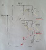
Is this the correct wiring of a 3-way asymmetrical parallel and series crossover? I.e. should the inductor for the LF (series) woofer be on positive side (before element) or negative side (after)?
The HF tweeter and MF midwoofer are in parallel (with tweeter polarity reversed to keep in phase). The HF has a second order crossover around 2400 Hz.
The MF has a first order crossover (one coil plus a Zobel filter).
The MF and the LF are in series with negative terminal of MF woofer connected to positive terminal of the LF woofer.
The LF woofer has a first order crossover (one coil). Assume the two coil values will be summed for LF woofer if the shown series woofer schematic is possible.
Attachments
Last edited:

I would keep everything in parallel configuration, as it seems that series connection is not well understood ...
The MF -the midrange, I suppose- hasn't any high pass before it, so it will receive the same amount of bass delivered to the LF. But not in this special case. Hazardous material in there !
The MF -the midrange, I suppose- hasn't any high pass before it, so it will receive the same amount of bass delivered to the LF. But not in this special case. Hazardous material in there !
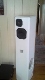

So those are the existing speakers, being the LF a side mounted bass enhancer which is mildly filtered by the 8 mH inductor ?
A way to test the amplifier's ability to drive low loads is to put your hand on the heatsinks!
If they get too hot at low-medium power it means that the power devices cannot withstand the high current for long periods .
With 8 Ω speakers it's not the case, they're ok for every amplifier.
Yes, the crossover has to be designed in order to predict if there are any impedance falls in any band, because of the reactive behavior of driver together with the passive components.
This schematic is what made me unsure where in the network the LF low pass coil should be wired in a series configuration.
Why and how of serial crossovers
Why and how of serial crossovers
Eliminating all the extra networks, a 1st order series XO is very easy, as the parallel type;
the drivers must be in series and the inductor and capacitor are in parallel to each driver; the driver itself exhibits an inductance ( it has a coil ) and influences the parameters of the network. So the paths of the currents are determined by the ability of the passive components to transfer only treble ( caps) or bass ( coils).
the drivers must be in series and the inductor and capacitor are in parallel to each driver; the driver itself exhibits an inductance ( it has a coil ) and influences the parameters of the network. So the paths of the currents are determined by the ability of the passive components to transfer only treble ( caps) or bass ( coils).
Hi,
The schematic is wrong.
For series with with no high pass on the mid you put
a capacitor across the bass unit for an unusual 2.5 way.
The two units wired in series.
Parallel with the inductor in series with the bass is a standard 2.5way.
They will sound very different, the latter a lot more bass.
rgds, sreten.
So if just doing 2.5-way parallel XOver instead, will the tweeter still be inverted polarity?
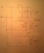
Schematic changed to parallel in first attached drawing.
Plus an example of what I assume the serial schematic should be like?
Schematic changed to parallel in first attached drawing.
Plus an example of what I assume the serial schematic should be like?
Attachments
Last edited:
- Status
- Not open for further replies.
- Home
- Loudspeakers
- Multi-Way
- 3-way asymetrical parallel and series crossover