hello to everyone,
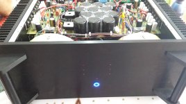
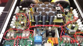
i would like your suggestions about my power amplifier. My power amp uses the irf240/9240 pairs. i have six channel in the same chassis. Each channel uses 4 pairs of irf's (total 8 per channel) . So on each heatsink i have 24 fets. Each channel is rated 200w/8ohms. I use 3 toroid transformers (one per 2 channels) 600va each. The amplifier rail voltage is +-70vdc. The bias is set at about 55ma per device.
today i thought, because the amplifier is used to power a 3 way active speakers, that maybe, and here i want your opinion, would be better to use only 2 pair of fets on the midrange/tweeter channels (or even 1 pair on the tweeter) and then i would be able to bias at 100ma which i think will be better. then i will have 200w+100w+100w(50w) per channel which is enough. Now i cannot bias it as high because the temperature is rising too much. What do you think about it?
Of course the voltage rails will still be 70vdc even with the only 2 pair fets. The amplifier gain (very important) will be the same am i right?
what would i earn by lowering the voltage rails to about 56vdc? (except the lower heat dissipation). I do not really want to rewind the transformers.
thank you
Attachments
Last edited:
Hi Ioannidis,
100W channel will run well even with +/-50W rails and 2 pairs of IRFP240/9240.
In this case, lower rails voltage is giving you not only less heat dissipation, but also keeping your power transistors within SOA (safe operation area) at all times.
If you, for example, leave only 2 pairs of outputs, running them at +/-70V rails, and by some reason your amp runs into clipping and /or the load at some frequencies is less than 8 ohm, the drain current of each transistor may be so high, that transistors go out of SOA and break instantly.
That's why, if you'd like to have a 50W channel with only one pair of outputs, you have to stay within some +/-36...40V rails.
One more consideration. Bias (and corresponding quiescent current).
4 x 55mA is not the same as 2 x 110mA. What is important here is the bias voltage, not the overall drain current. So, you need to maintain each output pair's quiescent current, not the overall current of all pairs in the amp channel.
I use IRFP240/9240 in a number of designs and my practical measurements show the optimal bias is around 80mA per pair, regardless of the number pairs I have per channel.
55mA per pair is still acceptable, although THD will raise a bit.
Great build by the way, in a nice Italian compartment (although 6 x 200W is a bit too much even for such a big box, unless some controlled fans are used) 🙂
🙂
My opinion - I would leave it as is. Hope this helps 😉
Cheers,
Valery
P.S. My build with +/-70V rails and 5 pairs of IRFP240/9240, although the front-end is powered via +/-50V regulators, limiting the output swing:
CF-FET V2.0
Sub-optimal energy-wise, but ok, assuming I'm running only 2 channels in such a box.
100W channel will run well even with +/-50W rails and 2 pairs of IRFP240/9240.
In this case, lower rails voltage is giving you not only less heat dissipation, but also keeping your power transistors within SOA (safe operation area) at all times.
If you, for example, leave only 2 pairs of outputs, running them at +/-70V rails, and by some reason your amp runs into clipping and /or the load at some frequencies is less than 8 ohm, the drain current of each transistor may be so high, that transistors go out of SOA and break instantly.
That's why, if you'd like to have a 50W channel with only one pair of outputs, you have to stay within some +/-36...40V rails.
One more consideration. Bias (and corresponding quiescent current).
4 x 55mA is not the same as 2 x 110mA. What is important here is the bias voltage, not the overall drain current. So, you need to maintain each output pair's quiescent current, not the overall current of all pairs in the amp channel.
I use IRFP240/9240 in a number of designs and my practical measurements show the optimal bias is around 80mA per pair, regardless of the number pairs I have per channel.
55mA per pair is still acceptable, although THD will raise a bit.
Great build by the way, in a nice Italian compartment (although 6 x 200W is a bit too much even for such a big box, unless some controlled fans are used)
🙂My opinion - I would leave it as is. Hope this helps 😉
Cheers,
Valery
P.S. My build with +/-70V rails and 5 pairs of IRFP240/9240, although the front-end is powered via +/-50V regulators, limiting the output swing:
CF-FET V2.0
Sub-optimal energy-wise, but ok, assuming I'm running only 2 channels in such a box.
Last edited:
hello,
first of all thank you for your answer and suggestion. It is quite difficult now to wind again the transformers. So you suggest not using 2 pairs with 70v rails. I wanted to try 2 pairs of irf's with 100ma bias current each. Now i have about 55ma each. I thought that the power is too much for mid and tweeter driver. I don't have the equipment to measure the crossover distortion with the 55ma and cannot compare with 100ma or more bias current. Yes i have read and have asked Holton (this is the av400 amplifier) and he said that 55ma is acceptable. Just wanted to try more bias and see if there is audible difference. 🙂
but as you said probably i will leave it as is. the heatsinks are at 45C at idle with the fans running. if i rise the bias at 100ma the temperature goes about 70C.
Last edited:
This has been discussed on this forum multiple times before, and you might want to search for those threads to read more about amplifier requirements. The answer is something like this:
AVERAGE POWER IN MUSIC SIGNALS: this is frequency dependent, lower in bass (believe it or not), peaking around 1kHz, and then falling again above that (generalizing, but the trend is true). The lowest and highest frequencies might be 10+dB lower in their AVERAGE power usage.
PEAK POWER: this is not really frequency dependent.
The above assumes all drivers in the system have the same voltage sensitivity and ignores effects like the "baffle step", loading of low frequency by room boundaries, etc. These are other factors that should be considered for your particular project.
Use the average power to size transformers, heat sinks, etc. keeping in mind that the midband has the highest power density and drivers not in the midband will use less power on average. The rail voltages should track the peak power (voltage) needs and should be more or less the same, all other things being equal.
Also - in class AB designs, more quiescent current per pair does not mean less distortion!
There is always an optimal value. In my amp, the minimal distortion is at around 80mA per pair (measured). It will grow if I change the quiescent current in ANY direction. Unless we really stay within class A region at all times. So... you are fine at 55mA per pair. If you make it around 150mA per pair, you'll end up with roughly the same distortion level 😉
There is always an optimal value. In my amp, the minimal distortion is at around 80mA per pair (measured). It will grow if I change the quiescent current in ANY direction. Unless we really stay within class A region at all times. So... you are fine at 55mA per pair. If you make it around 150mA per pair, you'll end up with roughly the same distortion level 😉
Hello
so, after a few years from my original post, i decided to procced with the modification of my power amplifier. I wanna ask you if is acceptable to connect some of these mosfets using wires. In this case i would have better mosfets placement on the heatsink and better heat dissipation. Would this have some negative effect? I mean wires from pcb to the mosfets, max. lenght about 3inches. If it is ok, tell me if they must be twisted or not.
thank you
Stray inductance must be kept to a minimum where large currents flow, so twist drain and source connections at the very least (the gate connection with its gate stopper resistor is less critical but should still be kept nearby) and use decent-diameter wires (maybe 24AWG / 0.25mm²?).I wanna ask you if is acceptable to connect some of these mosfets using wires. In this case i would have better mosfets placement on the heatsink and better heat dissipation. Would this have some negative effect? I mean wires from pcb to the mosfets, max. lenght about 3inches. If it is ok, tell me if they must be twisted or not.
- Home
- Amplifiers
- Solid State
- 3 way active system power needs