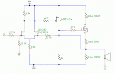
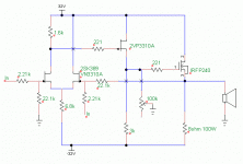
I have been reading Pass's article on DIY Op-amps and like one of his circuit examples (FIG 13): a JFET differential pair -> JFET volt amp -> MOSFET single ended or push-pull follower power stage (see attachment). I'm not sure the circuit will work as drawn as I merged 2 of Pass's circuits. Perhaps I should stick to some of Pass's single stage circuits.
Brock
Brock
Attachments
A couple of corrections:
- The output MOSFET must be N-channel, not P-channel.
- The JFET at the top should be P-channel and connected the other way up.
- You don't need the 1 Ohm resistor or the top 8 Ohm resistor.
- You need to add a resistor (e.g. 2.21K) between the 22.1K feedback resistor and ground. Add a capacitor (e.g. 100uF) in series with it.
What Vds is applied to the 389?
How much will this Vds vary when signal is processed?
The 389 are operating @ Id~2mA, what Idss do you plan to choose?
How much will this Vds vary when signal is processed?
The 389 are operating @ Id~2mA, what Idss do you plan to choose?
Last edited:
What Vds is applied to the 389?
How much will this Vds vary when signal is processed?
The 389 are operating @ Id~2mA, what Idss do you plan to choose?
I'm not familiar with the 389 or any transistors for that matter. I was thinking of using mpf102s at a few mAs. I know the mpf102s can handle up to 25V and I'm not sure if that would be exceeded in the differential pair. I may not know enough to get the circuit to work, which is why I asked for help.
Brock
What current is passing through the 1k6 Drain load?
What is the voltage on the Drain?
What is the Vgs at the Id?
What is the voltage of the Source?
What is the quiescent Vds?
What is the voltage on the Drain?
What is the Vgs at the Id?
What is the voltage of the Source?
What is the quiescent Vds?
It will get a lot more practical if all three resistors to the negative
rail are replaced by constant current sources.
😎
rail are replaced by constant current sources.
😎
- Status
- Not open for further replies.
- Home
- Amplifiers
- Pass Labs
- 3-stage Pass Inspired Amp

