Hello,
Hoping someone much smarter than myself can help...
I am looking at the possibility of doing a 3 stage fully differential opamp and running into some stability issues when applying a common mode voltage to force the output to swing around 0V.
Whilst I know this topology is possible with 2 stages (folded cascode IPS and VAS) I have not been able to find any reading material on a 3 stage design and am wondering if this is possible.
As per the attached simulation, I am appying the VCM via an error amp to the current mirror in the IPS, which ties the output to 0V.
The issue I am seeing, and the main reason why I am hoping for help, is that setting up the compensation of the amplifier to a point that measures as stable in .ac, in .trans the circuit is completely unstable. Which leads me to beleive I have the worng end of the stick, or have drawn it incorrectly.
There is also significant VHF instability caused by the VCM amplifier which I can not tame, almost as if the phasing of the amp is incorrect, but I am 'sure' that it is correct.
I am wondering if I have missed something obvious, or maybe this topology is not possible the way I have planned it out.
All/any comments hugely appreciated.
B
Attachments
I cannot read .asc files (old school tech), but instabilities in hf are mainly caused by nasty poles turning phases around as if wrong as noted. Two stages can be made stable, three is even more complex and maybe the reason for finding hard of examples: left behind or unsuccesfull topologies.
Further readings about filters (poles and zeros) and hf issues, by nature more difficult to grasp, are recommended nevertheless.
Further readings about filters (poles and zeros) and hf issues, by nature more difficult to grasp, are recommended nevertheless.
Can you reduce the gain in each stage to see how it behaves? Is it possible to insert resistors between each stage as hf-stoppers?
Why 3 stages? You need the gain I guess. How bout a compound amp with an external prestage? Not enough real estate?
Why 3 stages? You need the gain I guess. How bout a compound amp with an external prestage? Not enough real estate?
I put together a sim using voltage dependent current sources for the VCm error amp and input stage and it did tame the stability but I could never bring down to something usable - which elad me here as I can only assume I have put it together incorrectly.
It is really more of an investigation more than anything else, a similar approach works very well in 2 stages and I was curious as to why it is so difficult with 3.
I will go over it again and reduce the gain right down to see where it ends up. Thanks for the advice
It is really more of an investigation more than anything else, a similar approach works very well in 2 stages and I was curious as to why it is so difficult with 3.
I will go over it again and reduce the gain right down to see where it ends up. Thanks for the advice
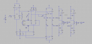
This is a very sensitive design really. Resolution is low but it is clear enough for me now.
Actually it appears to me as a standard two stage amp with current output buffer, full symmetrical. The only addition is the summing differential most left on the drawing. It is to correct dc at both outputs by injecting its resulting signal in the load (= current mirror) of the input differential.
Disconnect the 220 ohm resistor from this dc-diff to the input-currentmirror and add two resistors of say 33k in between the diode-legs to gnd. That would keep the output near zero but you have left out the 'third man'. See if this config is hf-stable. If so connect the 220R again and compare. If ok remove the two 33k's and compare.
Try to improve the drawing (resolution! and A4/Letter size preferably).
Thanks, I am not sure I follow where you are suggesting to add the 33K resistors - could you expand please?
Way better, thanks.
The mentioned 220R is R1.
33k's from in between D5-D6 and D1-D2.
These two will reduce openloop gain, but keeps the outputs within dc limits too. (Forcing near zero volt.)
HF gain reduction between collectors Q6-Q7 with RC network (150p-100R) is recommended. Lots of trouble can start from there with the Q27--Q30 dc injector.
-> Add a serious cap on bases Q27 & Q28 to correct for dc only (best advise from me now). <-
- Home
- Amplifiers
- Solid State
- 3 stage fully differential opamp - possible?