Hello, I need your precious advice on these 3 pre amp.
One uses nuvistor, the second is a very simple cascode and the last one is the Kaneda pre.Of the Kaneda pre I only need the line pre.
I will use the best components, so I would like to know yours advices.
Thanks.
One uses nuvistor, the second is a very simple cascode and the last one is the Kaneda pre.Of the Kaneda pre I only need the line pre.
I will use the best components, so I would like to know yours advices.
Thanks.
Attachments
Nuvistors, aka "acorn" tubes, are pretty cool, but you'll need to make sure that you can get the tubes and the sockets if you choose to go ahead with that design.
Grey
Grey
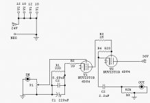
I've choosen the Kaneda for my preamp (a design a bit different than the one you posted; Mr. Kaneda has literally hundreds of preamp designs published). I needed RIAA and line preamplification, and like the approach he used.
I have found the nuvistor at the shop, pretty expensive though,but I never heard any pre using them, so I am not so sure about them.
About the Kaneda, does it sound good?Can you compare it to which other pre? Did you use substitute ( 2sa640 and 2sk240 are not easy to find)?
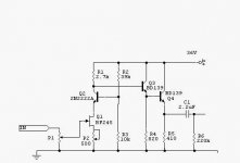
The cascode circuit is very simple: the fet is used to gain in current, the 2n2222a to gain in voltage; it is used in common base, so it has extreme linearity and wide frequency response.The 2 bd139 are used as impedence adaptor: using only one bd139 the output impedance is about 25 ohm, using 2 bd 139 the impedence is around 1 ohm.
The local retroaction is of 3 dB only.This circuit is very sensible to the quality of the components used.
What do you think about it?
Claudio
About the Kaneda, does it sound good?Can you compare it to which other pre? Did you use substitute ( 2sa640 and 2sk240 are not easy to find)?
The cascode circuit is very simple: the fet is used to gain in current, the 2n2222a to gain in voltage; it is used in common base, so it has extreme linearity and wide frequency response.The 2 bd139 are used as impedence adaptor: using only one bd139 the output impedance is about 25 ohm, using 2 bd 139 the impedence is around 1 ohm.
The local retroaction is of 3 dB only.This circuit is very sensible to the quality of the components used.
What do you think about it?
Claudio
Claudio,
A comment on the first circuit. It may perform better using fewer transistors. Being a pre-amp I assume it will be driving +/- 2V or so into >10kohms. This is a peak current of 0.2mA. For good margin let's multiply this by 10 to give 2mA. The circuit shown looks like the Q4 bias is some 20mA to 40mA - overkill?
Instead of using two beefy BD139s I think the circuit would sound better using a single gazelle-like transistor such as a BC549. It has typical hfe 520, ft 300MHz and 500mW dissipation. The value of the emitter resistor should set the bias to, say, 10mA. The output resistance would be <10 ohms - plenty low enough for a 10k load. This saves a couple of parts and reduces the number of distortion generators.
BAM
Preamps
The Kaneda preamp looks good. The matched Fet diff pair can be the 2SK389 in place of 2SK240. This a great sounding Fet pair and used John Curl and Passlabs. The bipolars can be Zetex ZTX450 and what ever the Zetex pnp comp is. The Zetex bipolars are used in several Hi End designs. Zetex also makes some wonderful small signal mosfets. (hint they are in one of Mr. Pass's
articles.) Another couple of small signal bipolars are the 2SC17775 and 2SC872. The 2SK170 are also excellent jfets and neat differential pairs when matched. All these are fairly easy to find in DigiKey or MCM electronics. Check out the jfet articles at
www.borbelyaudio.com also. I am fairly certain that that
the nuvisitorschematic has errors These are great devices but are TUBES. They are very microphonic. CJ use to use them in a MC preamp. The PCB was mounted on Rubber bands for isolation!! I read that tube was developed for the front end of high speed oscilloscopes.
H.H.
claudio said:About the Kaneda, does it sound good?Can you compare it to which other pre? Did you use substitute ( 2sa640 and 2sk240 are not easy to find)?
I haven't built the Kaneda yet (right now i'm working in the case for my amp 🙂 ), but it's reputed to sound excelent. I'll post the other Kaneda design i have; it uses only a cap in the feedback path for stabilization, the rest of the circuit is identical... i got these schematics from a website a good while ago, but lost the link.
BTW, i've simulated the Kaneda with "off-the-shelf" devices (BC546/556 for the bipolars and two 2N4393 for the dual FET), and, at least there, it performs ok. I also have trouble finding japanese semiconductors here, but i think any quality audio devices (motorola f.ex.) would work right.
Attachments
Some questions to your first design:
Doesn't the first transistor of the output darlington have to be a PNP device (like in the Hiraga Monster) ?
Doesn't the output capacitor have to be much bigger? ( I would use at least a 10uF electrolytic with a 100k resistor to ground, because I think small foils sound worse when you have a significant DC offset )
Did you design it actually ? Or build it ?
I like it, but I still have doubts...
Klaus
CJ used a 6CW4...not the same tube. Yes, it was microphonic to a degree. Whether these tubes are microphonic or not, I couldn't say.
Grey
Grey
6CW4
Grey is right on the CJ tube selection and the 6CW4 is very microphonic but a good sounding tube. Why don't you find the mistake in the schematic while you're at it........
H.H.
Grey is right on the CJ tube selection and the 6CW4 is very microphonic but a good sounding tube. Why don't you find the mistake in the schematic while you're at it........
H.H.
<i>Lisandro_P</i> found you lost link, I think; <a href="http://member.newsguy.com/~stigerik/kaneda.html">Kaneda Link</a>
<a href="http://www.jls-info.com/julien/audio/index1.htm">Le coin de l'audiophiles</a> "Le préampli Kanéda" uses 2x 2SK170s
Toshiba no longer list the 2SK389 (or 2SJ109) on their Japan website, has it gone out of production?
Below is a Virtual opamp by Kenada method, the pics a link.
<a href="http://member.nifty.ne.jp/MUTSU/e/hp021.htm"><img src="http://member.nifty.ne.jp/MUTSU/e/gif/fig21b.gif" ></a>
Regards
James
Kaneda
It looks like the schematic is in error the bases of the must be tied to a lower voltage than the positive rail. Open the trace and install a 10K resistor between the bases/47K node and the
positive supply. I think this circuit would work with about +15V and -15V rails. The 389 and 109 should still be available. I bought mine from MCM Electronics.
http://site.pcmagazine.com.tw/audio/parts/parts.htm
H.H.
About the nuvistor scheme, for V1 a 6CW4 or 7895 or 6DS4 can be used; for V2 :7586 or
6DW4. Maybe the error Harry was talking about is the V2 type: in the scheme
it is 6DV4 instead of 6DW4 ; it is my mistake.
About nuvistor microphonicity, I always read that nuvistor has little or none of it, thanks to the
fact that the electrods are concentric.As far as I know only Musical Fidelity continues
using these devices.
About the Kaneda I saw the schematic in here: http://www.infomaniak.ch/~bonavolt/index.html.
I have heard lot of people saying good things on it.
And now let's talk about the cascode pre.
The circuit was desogned by Luca Chiomenti, an italian guy that writes for the magazine "Fedelta' del suono".
Klaus, the output capacitor can range from 2.2 to 10, I think the best way is to make sound test to decide the right value;
the important is to use a very good quality cap ( polyester, polystirol ,etc).
The darligton created by the 2 follower (Q3 Q4), has a resistor connected to ground on Q3 : this makes
a strong current to flow through Q3, so that it works in a more linear zone.
BAM suggested the using of one BC549 instead of 2 BD139: The Vce of the BC549 is 30 Volts, isn't it too low?
About R1 value, its range goes from 2.7K to 3.3K, depending on Q1 IDSS: low IDSS(<7mA = 3.3k;
high IDSS(>7mA)=2.7k. It is important to use similar IDSS for the 2 channel.
Claudio,
My philosophy is, all things being equal, to minimize the number of distortion generators in the signal path. Each semiconductor introduces some distortion and the potential for instabilities. I'd argue against Q2 if it were not there to minimize distortion from Cdg of the JFET by fixing Vds.
Regarding P2 I would think the main need is for the JFET input capacitances and transconductances to be matched, which may or may not be the case when Id is matched.
In any case, with this circuit you need to have a very well-regulated, low noise supply because any supply noise/distortion will be added to the output signal. You may want to consider decoupling R3 with a 100nF to stop psu noise modulating Vgs or causing instability.
A note on psu decoupling. I often find it informative to imagine the circuit has a really "loose" psu - one that flaps around as current changes. Then think about how this might affect the circuit performance. This comes from my experience of power amp design where this is an even bigger problem. Consider that much psu noise is generated by the circuit itself and contains bits of the music signal and some distortion and some random noise, all mixed together. Now imagine that Q4 draws a pulse of current. This will cause V+ to dip slightly, which will cause Q2 base and emitter (and collector) to dip slightly. In turn, the dip is seen across the drain-gate of the JFET causing a gate current due to Cgd. This current will tend to lower Vgs and turn the FET off which will lead to Q4 turning on harder and drawing more current from V+. Spot the potential positive feedback loop. I am not saying this circuit would misbehave in practice but you must keep an eye out for these potential, unintended feedback loops and sources of unwanted noise. In really high-end systems these minor effects become audible. Hence decouple R3.
BAM
Q2 is needed in the circuit for the usual benefits of a cascode voltage gain stage. It will also improve power supply rejection as the output impedance of the first stage looking into the 2.7k resistor will be much higher. The 2SK170 would be a good sub for the JFet and a Zetex ZTX450 for Q2 and Q3. I would adjust the pot for about 3 mA through the Fet and then replace it with a good resistor. I believe Mr. Pass has an article on cascodes on his web site as well as Mr. Borbely. This circuit would be even better with all fets. Maybe I'll post one.....
H.H.
H.H.
tvi said:<i>Lisandro_P</i> found you lost link, I think; <a href="http://member.newsguy.com/~stigerik/kaneda.html">Kaneda Link</a>
Thanks a bunch! 😀
Harry is right, Q2 is part of the cascode circuit, it has to be there.
P2 works togethere with R1: the 2's gives the gain,that should be between 5 and 8, and P2 regulates the sleep current ,therefore moves the
voltage on Q2 collector: the effect gives the amount of the clipping simmetry.On Q2 collector there should be 2 volts more than
the half of the circuit voltage( 36/2+2=20)
For sure the PSU has to be well filtered and stabilized: any ready to build suggestion for the PSU?
Harry, using the 2SK170 which advantage could give? This JFET noise figure is 1 db (typical) while the BF245's is 1.5 db: not a big improvment.
The Yfs is much better in the 2SK170: will it means that the input impedence will be higher using it?
I couldn't find the cut-off frequency of the 2Sk; the BF's is 700 MHz.
Harry you suggested to use all Fets : but since Q2 is used for voltage gain, isn't bipolar more suited for this job?
Claudio
2SK170
The 2SK170 is a low noise audio Jfet by Toshiba designed for use in low noise preamplifier circuits. It and the 2SK389 dual fet pair by Toshiba are probably the two best sounding transistors for preamps and amp front ends made. They have the lowest noise
and highest forward transconductance of any jfets that I know of.
The K170 or K389 have been used by John Curl, Jeff Rowland,
Erno Borbely, Steve McCormak, and Nelson Pass. These
gentlemen are part of the short list of the worlds best solid state
audio designers. The BF245 is an RF transistor. The K170 has 4
times the transconductance and low noise at audio frequencies.
Noise figure is only of merit if compared at the same frequency
and source impedance. I have built and modified dozens of audio circuits with these parts. They sound great. Go listen to some!
The data sheets for the K170 and K389 are at:
http://site.pcmagazine.com.tw/audio/parts/parts.htm
I should get paid for advice this good. Give it away and everyone thinks it is not worth anything.
H.H.
- Status
- Not open for further replies.
- Home
- Amplifiers
- Solid State
- 3 preamp to choose from