I've been kicking around the idea of a 3 phase BLDC motor and controller for a couple of years now. I've experimented with a lot of the Hurst AC synch motors, but vibration was ALWAYS a problem. I found the Hurst motors to be very inconsistent in build quality. Problem with the BLDC approach, I could never find a motor that I liked or that was cost effective, until a recent trip to Japan when I found a fantastic 3 phase BLDC motor in the Akihabara electronics mart. Inspired by a couple of conversations with Mark Kelly on the subject, I finally decided to pull the trigger on the controller now that I found a suitable motor, mainly as a non-commercial project-- just to see what was possible.
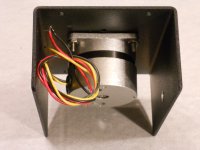
The motor is 24V / 12W / 1500 RPM and has about 4x the torque rating of a 10W 600 RPM Hurst AC synch motor, although it is smaller diameter (45mm vs 59mm) and only slightly longer (60mm vs 40mm). When I spin the motor by hand, I feel no cogging at all, even though it has iron stators and a PM rotor. The motor uses precision ball bearings that are pressed onto both ends of the shaft so there is no end play at the pulley at all. I think this is one of the reasons the Hurst motors are so noisy; that and they only have one bearing at the top of the shaft, the magnet/rotor is left to fly around at the bottom with no support. I've built 2 phase controllers for the Hurst motors, but of the 6-8 motors I have, not all of them would work; some of them would start vibrating horribly as they got up to speed unless I damped the motion with my thumb. I contacted Hurst about this and they said that was typical and that I should attach a small collar to the shaft to control end-play like VPI does on some of their motors. Didn't seem like a very workable solution to me. The bearings in the BLDC motor initially gave me pause, until I fired it up and realized it was far quieter than any of the Hurst motors I have. The construction of the stators is similar to AC induction motors with all of the windings on one core assembly rather than on 2 bobbins like the AC synch motors (another source of vibration in the latter). The BLDC bearings are sealed and never need lubrication; and unlike friction bearings, they can handle much higher radial loads without having to replace them when they wear. The motor runs quieter than any of the Hurst motors I have and is comparable to the 2W Premotec motors for noise.
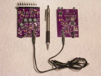
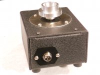
The controller is the same basic design as my other controllers (DDS based) except that it has 3 phases instead of one. I also needed to adjust the output voltage and phase based on the speed of the motor and the torque required. Having independent control of all three elements creates an extremely smooth rotation with much more torque than an AC synch motor. The other HUGE advantage is the range of speed control with this method: With the Hurst AC synch motor, I would be lucky to get 3:1 speed range, even when driving both phases with quadrature signals. The high end (90Hz max) would have almost no torque and the low end (30Hz) would cog excessively. With the BLDC motor, I can easily get 100:1 speed range running the motor from 15 RPM to 1500 RPM (<1RPM to ~83 RPM at the platter) and the torque is surprisingly high even at 78 RPM. I start the motor at ~5Hz (4.2 RPM at the platter) and can ramp up to 93.6Hz (78 RPM at the platter) in a matter of seconds with zero burn out on the belt and all 3 speeds (33/45/78) using the same pulley. The controller drives a 3 channel class D amp powered by a 24V 1A wall wart. The amp fits in the same sized housing as the controller (about the size of a pack of cigarettes) and never gets over 100 deg F.
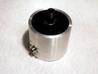
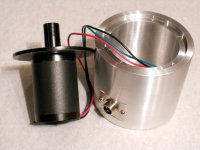
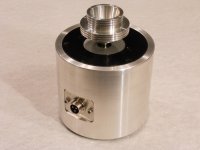
Since I have complete control over the phase of the 3 windings, I can also control the direction of rotation in software. I can easily switch between CW rotation for belt drive or by putting a rubber grommet on the pulley and switching to CCW, use it as a direct rim drive. I had a local machine shop turn an aluminum housing from a piece of 3.5" solid aluminum bar; the standard SAMA housing on my Scout was too wide to allow the motor to get close enough for the pulley to make contact with the platter. I wasn't happy with the vinyl grommet so I stuck with belt drive for now, but I'm going to keep looking for a softer silicone washer to use for rim drive.
I did some listening tests with the new motor vs the Hurst AC synch motor on a VPI Scout table and there is a noticeable improvement. Dynamics definitely took a step or two in the right direction. Because the motor has virtually no vibration, the noise floor seems to have dropped as well and the back ground is eerily quiet. Detail and clarity seems to have improved, but only because they don't get buried in the noise as before. I don't think it change the sonic signature of the table, the detail was always there, I just couldn't hear it as well. I wished I had found this motor earlier, but now that I have it, I'll never go back to AC synch motors again.
The motor is 24V / 12W / 1500 RPM and has about 4x the torque rating of a 10W 600 RPM Hurst AC synch motor, although it is smaller diameter (45mm vs 59mm) and only slightly longer (60mm vs 40mm). When I spin the motor by hand, I feel no cogging at all, even though it has iron stators and a PM rotor. The motor uses precision ball bearings that are pressed onto both ends of the shaft so there is no end play at the pulley at all. I think this is one of the reasons the Hurst motors are so noisy; that and they only have one bearing at the top of the shaft, the magnet/rotor is left to fly around at the bottom with no support. I've built 2 phase controllers for the Hurst motors, but of the 6-8 motors I have, not all of them would work; some of them would start vibrating horribly as they got up to speed unless I damped the motion with my thumb. I contacted Hurst about this and they said that was typical and that I should attach a small collar to the shaft to control end-play like VPI does on some of their motors. Didn't seem like a very workable solution to me. The bearings in the BLDC motor initially gave me pause, until I fired it up and realized it was far quieter than any of the Hurst motors I have. The construction of the stators is similar to AC induction motors with all of the windings on one core assembly rather than on 2 bobbins like the AC synch motors (another source of vibration in the latter). The BLDC bearings are sealed and never need lubrication; and unlike friction bearings, they can handle much higher radial loads without having to replace them when they wear. The motor runs quieter than any of the Hurst motors I have and is comparable to the 2W Premotec motors for noise.
The controller is the same basic design as my other controllers (DDS based) except that it has 3 phases instead of one. I also needed to adjust the output voltage and phase based on the speed of the motor and the torque required. Having independent control of all three elements creates an extremely smooth rotation with much more torque than an AC synch motor. The other HUGE advantage is the range of speed control with this method: With the Hurst AC synch motor, I would be lucky to get 3:1 speed range, even when driving both phases with quadrature signals. The high end (90Hz max) would have almost no torque and the low end (30Hz) would cog excessively. With the BLDC motor, I can easily get 100:1 speed range running the motor from 15 RPM to 1500 RPM (<1RPM to ~83 RPM at the platter) and the torque is surprisingly high even at 78 RPM. I start the motor at ~5Hz (4.2 RPM at the platter) and can ramp up to 93.6Hz (78 RPM at the platter) in a matter of seconds with zero burn out on the belt and all 3 speeds (33/45/78) using the same pulley. The controller drives a 3 channel class D amp powered by a 24V 1A wall wart. The amp fits in the same sized housing as the controller (about the size of a pack of cigarettes) and never gets over 100 deg F.
Since I have complete control over the phase of the 3 windings, I can also control the direction of rotation in software. I can easily switch between CW rotation for belt drive or by putting a rubber grommet on the pulley and switching to CCW, use it as a direct rim drive. I had a local machine shop turn an aluminum housing from a piece of 3.5" solid aluminum bar; the standard SAMA housing on my Scout was too wide to allow the motor to get close enough for the pulley to make contact with the platter. I wasn't happy with the vinyl grommet so I stuck with belt drive for now, but I'm going to keep looking for a softer silicone washer to use for rim drive.
I did some listening tests with the new motor vs the Hurst AC synch motor on a VPI Scout table and there is a noticeable improvement. Dynamics definitely took a step or two in the right direction. Because the motor has virtually no vibration, the noise floor seems to have dropped as well and the back ground is eerily quiet. Detail and clarity seems to have improved, but only because they don't get buried in the noise as before. I don't think it change the sonic signature of the table, the detail was always there, I just couldn't hear it as well. I wished I had found this motor earlier, but now that I have it, I'll never go back to AC synch motors again.
Attachments
Apples and Oranges. The SL1200 is DD, this is for belt drive/rim drive tables.
What is the torque rating for the SL1200 motor?
What is the torque rating for the SL1200 motor?
Forgive the truly ignorant question, but I'm having trouble putting DC and 3 phase together. Is the 'phase' component indicating how many controller-timed circuits provide DC the coils? Hence a motor whose rotor contains 3 sets of 2 opposed magnets would use one 'phase' pulse per matching coil per revolution.
Thanks for any illumination available.
skip
Thanks for any illumination available.
skip
Very interesting Pyramid. I love it when folk transfer technology from one field to another (and share it).
I considered BLDC for my turntable build but having no experience of BLDC motors I wrongly inferred that they were (only) high revving thus not suitable.
Skip Pack - like so many things, BLDC is a marketing term. It's a brushless (therefore half-right!) motor usually powered by a DC battery through a controller, the controller switches the phases while sensing the rotor position.
Russc and Skip Pack-
BLDC (aka EC motors) are an interesting type of hybrid. Normally, they are used in industrial applications and the controllers are DC switching (trapezoidal waveform) type. The DC voltage level determines the speed, and Hall Effect sensors signal the control circuits when to switch (or commutate) the drive signal, so they behave like conventional DC motors in that the voltage drives the speed and commutation is done electrically instead of mechanically. This type of drive circuit produces a lot of torque ripple (cogging). It also requires feedback from the motor to control the speed.
In these types of motors, there are 3 windings spaced 120 deg apart so they can be driven instead by AC sinewave signals with 120 deg phase shift between them and if done so, they behave like AC synchronous motors with the frequency determining the speed. If driven this way, the amplitude of the AC signal is still important and should closely approximate the DC level for the same speed. For lowest noise operation, the phase relationship of the 3 signals is also important. By controlling all three aspects (frequency, amplitude and phase angles) the motors can be controlled with extreme speed accuracy and very low noise. As far as I know, there are no other belt drive or rim drive tables using this type of motor. The advantages are: Wide speed range, high torque, low vibration and very good speed accuracy.
IME, this represents a drive system for BD or rim drive that is an order of magnitude better than using AC synch motors with regards to low vibration and higher torque while maintaining the advantage of frequency determined speed.
Billshurv- The SL1200 motor is a low torque BLDC motor driven as a DC motor; i.e. it uses a feedback mechanism for speed control. My implementation is a feedforward system for motor speed control.
Billshurv- The SL1200 motor is a low torque BLDC motor driven as a DC motor; i.e. it uses a feedback mechanism for speed control. My implementation is a feedforward system for motor speed control.
The motor in the 1200 is the same as the SP15 just at lower voltage. SP15 is 3kg.cm and would accelerate the platter to speed in less than a revolution. How much more torque do you need? the SP10 at 16kg.cm was barking and could get a 10kg platter to speed in under 1/4 revolution.
I am interested in what the advantages are in your drive system. Like most things in hifi there is so much **** spoken about motor drive nice to consider something not ruined by marketing to the true believers 🙂
Hi Pyramid
Have to contain my excitement about this, so will wait for you to share further developments on this, but am seriously hoping you make this available.
I have purchased a couple papst aussenlaufer motors with the hope that someone would offer a high quality 3-phase supply that I could use to complete my rim drive table. Unfortunately, since Mark Kelly ceased making such supplies, there doesn't appear to be any available solutions.
Now, maybe a smoother, quieter, torquier motor than the esteemed papst motor ??
Very cool !!
The motor in the 1200 is the same as the SP15 just at lower voltage. SP15 is 3kg.cm and would accelerate the platter to speed in less than a revolution. How much more torque do you need? the SP10 at 16kg.cm was barking and could get a 10kg platter to speed in under 1/4 revolution.
I see. I have no intention of turning this into a "BD vs DD" thread. Surely, there must be plenty of other threads where these arguments have been made already?
My O/P was in regards to replacing a Hurst AC synch motor with a BLDC motor. My turntable is belt drive and I have no desire to convert it to DD, so I am stuck with a belt drive or rim drive system. Changing motors has made a definite improvement.
I am interested in what the advantages are in your drive system.
As I stated in my previous post:
IME, this represents a drive system for BD or rim drive that is an order of magnitude better than using AC synch motors with regards to low vibration and higher torque while maintaining the advantage of frequency determined speed.
I would add: There is zero burn out on the belt, even when starting in 78 RPM mode with a heavy platter; mine is only 8lb, but it would just as easily start a 20lb aluminum platter without the familiar "chirp" on the belt (using a 600 RPM pulley or 300 RPM pulley).
Neither have I. But you asked about torque so I looked up torque for you. You can use an SL1200 motor to drive a belt if you want after all.I see. I have no intention of turning this into a "BD vs DD" thread. Surely, there must be plenty of other threads where these arguments have been made already?
And my (unanswered) questions was merely as to what this particular BLDC motor has over a repurposed technics motor, as I have a few I picked up for a few pounds with cheap turntables attached.My O/P was in regards to replacing a Hurst AC synch motor with a BLDC motor. My turntable is belt drive and I have no desire to convert it to DD, so I am stuck with a belt drive or rim drive system. Changing motors has made a definite improvement.
Are we at a misunderstanding or do you just not want to have a discussion about this? I'm not a motor drive expert so not heard of 'feedforward' used in motor drives before other than as a form of predisortion of the drive signal.As I stated in my previous post:
Do you have an test records? There is quite a collection of measurements now of 3kHz test tones off different decks that members are collecting. would be a nice data point to add this to the mix.IME, this represents a drive system for BD or rim drive that is an order of magnitude better than using AC synch motors with regards to low vibration and higher torque while maintaining the advantage of frequency determined speed.
Just to be doubly clear.
I am not wanting to compare DD/RIM/Belt, just BLDC motors and different motor drive methods. I was hoping for some discussion around the measured advantages you have seen with your choice of drive and an understanding of what you meant by feedforward. However the internet being what it is things always get misinterpreted. 🙁
Sorry if I misunderstood your posts. They seemed confrontational to my reading.
In theory, you could re-purpose an SL1200 motor and use it as a belt drive. Since you have a number of these, I would encourage you to do so and post your results (I for one, would like to see what this would look like). Since torque=Power/Speed it would be interesting to measure the torque of one of these motors at 600 RPM vs 33 RPM, keeping power consumption constant. Given that the SL1200 motor was probably optimized for slow speed operation, I wonder if it would be capable of running at 600 RPM (or higher as would be required for 45 or 78 RPM platter speed). The SP10 motor has 20 poles so it would require 100 Hz for 600 RPM. The motor was designed to run at 5.555 Hz for 33 RPM platter speed (this is what prompted my comment re apples and oranges).
If I understand the drive method used on the Technics tables, they are PLL based which uses a feedback system which can be prone to "hunting", depending upon the loop bandwidth (at least the MK2 was, I believe the MK1 was a DC servo control). A DDS based system does not use feedback to maintain a stable frequency, it is a type of feedforward system.
Regarding measurements, I do have a test record but have not done any tests with it. As far as speed accuracy, I use a tachometer with 3 decimals places of resolution. The accuracy is as good (if not better) than when using AC synch motors. I doubt there is any MEASURABLE improvement in W&F with the new motor, however, what I am hearing may be attributable to improved speed stability.
The other improvement in sound is related to dynamics (or what some refer to as PRaT) and may be the result of higher torque and/or using multiple belts.
No problem, if things can be misread, they often are. I do the same sometimes 🙂
If you can record a 3kHz tone into a PC I am sure George would happily analyse it.
Some technics are PLL, others aren't, but most you can turn lock off and there are pages of argument with no measurement on which is better. I'm not a believer in the groove actually slowing the platter down appreciably so I just view the loop as a good way to get to speed quickly.
I'm trying to get a contact in TI to slip me a DRV8312 eval board to let me play around with different options. Similar to the board you have you can adjust everything. But will be a little while before it gets running due to current project backlog. But as soon as I do, will see how fast it can go and if the bearing will hold out.
In the 'interest' pile is an old JVC which has the controller (and possibly pancake motor) originally designed for floppy disks. 2 phase drive but should do the speed.
DSP motor control
I've looked at some of the TI solutions, as well as Analog Devices and a rather interesting chip from PMD (MC73110 dedicated DSP motor controller). The main thing I didn't alike about any of these (besides cost and complexity) was they all required an optical encoder for speed feedback. I think the focus of most of these designs was lower vibration over speed accuracy. While both are important, IMHO accurate speed control and adjustment is the most important factor and vibration reduction is still achievable even while focusing on the former.😎
I've looked at some of the TI solutions, as well as Analog Devices and a rather interesting chip from PMD (MC73110 dedicated DSP motor controller). The main thing I didn't alike about any of these (besides cost and complexity) was they all required an optical encoder for speed feedback. I think the focus of most of these designs was lower vibration over speed accuracy. While both are important, IMHO accurate speed control and adjustment is the most important factor and vibration reduction is still achievable even while focusing on the former.😎
They're apples of very different magnitudes, 1500 RPM vs. 33.33 RPM.They are both BLDC so why are they not both apples?
And for reference:
https://en.wikipedia.org/wiki/Brushless_DC_electric_motor
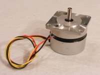
This project really has me thinking. The BLDC motor I found overseas worked beautifully, but it was just a tad too tall for the Scout SAMA housing and also would not fit in a VPI Classic table. I found a US supplier of similar motors and they had a version with the same basic electrical rating (12W, 24V, 1500 RPM) but in the same form factor as the Hurst 59mm series. Unfortunately, it also has a 1/4" shaft, but I still have some pulleys left over from the 300 RPM motor project that I was looking at 2 years ago and they work a treat!
I did have to modify the firmware just a bit as the motors were not identical electrically, but close. I was able to mount the new motor in my Scout SAMA housing using slightly longer hardware as the mounting flange is much beefier on the new motor. I replaced the IEC inlet with a small plate and mounted the 3 pin low voltage connector onto the plate.
I was also able to mount the new motor in the cylindrical housings I had made with only minor modifications to the mounting flange of the motor.
The new motor is just as silent as the original with absolutely no vibration felt or heard at the motor when running. It also has the same torque rating as the original which is ~2x the torque of the Hurst 300 RPM motor of the same size. Since I'm starting at 5Hz, the motor spins up to speed without chirping or slipping on the belt. The sense of increased dynamics is still readily apparent with the new motor as is the quieter background.
Next up, I want to mount the new motor in a VPI Classic plinth and do some listening tests.
Attachments
Please keep posting your project details, although I am running idlers (and heading in the direction of 3 phase AC motors) I still find this quite an interesting discussion.
¿BLDC motrors are situable for a turntable sevice? hummmmm.....
Are a PWM motor type, no like a classic and progressive sinus AC motor.
.... and ¿the "cogging" control between the magnetic poles and permanent magnets? ?????
I use this type of motor (BLDC) successful on my bicycles, but here....I dont know.
Cheers
Pyramid : escuse me... I dont read " they can be driven instead by AC sinewave signals with 120 deg phase shift ".... no PWM. Mínimal cogging.
Your are right. Excelent solution with tree phases at 120º .... I think is a very quiet motor for a TT.
Last edited:
This is exciting!! I am a long term VPI owner. I started with an HW19 in the mid '90's. I have been through the PLC and now use the SDS with a single motor fly wheel and super platter. In all of these years and various iterations, the Hurst synchronous motor has been the weak link, which most of the turntable ancillary gear has attempted to ameliorate.
I would love to solve the source of the issue, rather than throwing more "makeup" on the Hurst motor. Are you looking to add this to your product line or make it available, in some form, for us DIY'ers? Either way Please keep up this development. It is exciting!!
Cheers,
Geary
I would love to solve the source of the issue, rather than throwing more "makeup" on the Hurst motor. Are you looking to add this to your product line or make it available, in some form, for us DIY'ers? Either way Please keep up this development. It is exciting!!
Cheers,
Geary
Hi,
#12
Do You mean that the platter speed always deviates from the preset value with the speed feedback loops constantly trying to but never succeeding in finding the correct speed?
Well that is not the case.
The PLL evolved historically from other drive systems ... and so did the Technics and all other DD turntable drives.
The PLL-servo was just the culmination of that evolution process.
It began with the e-servos where coils within the motor were used to generate a speed-proportional signal (Technics Chip AN630).
With the first DUAL motors (EDS-1000 etc.) only one of the three phase coils was momentarily driven and the other two were used as sensor coils (like in a dynamo).
Technics drove all three coils and built another set of three sensor coils into the motor.
In both cases the sensor coil signals were summed with a Diode network, rectified and smoothed to generate a speed-related dc-voltage.
This voltage was then compared to a (switchable/variable) reference voltage with a difference amplifier, amplified and used to drive the motor drive coils.
The smoothing lowpass filter for the rectified sensor signal required long time constants for effective smoothing.
Hence the regulation speed was comparably slow.
So slow that a speed overshoot could occur.
The platter weight was therefore kept high to profit from the mechanical ´smoothing´ action of the inertia and to insure that the mechanical time constant was kept considerably higher than the electronical time constants.
Additionally Pioneer used advanced lowpass Filter circuits with reduced ´reaction time´ (variable damping LPFs) that combined between the faster reacting but overshooting LPFs with the slower but non-overshooting precise LPFs.
Due to the sensitivity to temperature, ageing, supply voltage etc. and the slow regulation speed the load regulation and speed constancy -short and long- time was only mediocre.
The next evolutionary step was the introduction of the frequency related speed control.
Here the speed sensor produced a speed related frequency signal.
Technics used dedicated coils within the motor again, Sony and Denon used a multi-pole magnetic layer printed onto the rim of the platter in conjunction with a tape-head.
Others used meandered sensor coils or optical sensors.
In any way was the sensor signal fed to a frequency-to-voltage converter which put out a speed related voltage, that then was compared to a reference voltage and so on.
The sensor signal was malmost completely free from the environmental influences the e-servo suffered from.
Also the required smoothing filter time constants became shorter, due to higher sensor signal frequencies and the introduction of sample-and-hold (S&H) circuits instead of RC-Filtering.
Higher frequencies and higher speed of the regulation loop lead to higher regulation precision and speed stability, short time as well as long time.
The high platter inertia was not needed any more and accordingly the platter mass reduced in weight.
The PLL-servo relied on the complete F-servo system and same Motor/F-Sensor-subassemblies and basically only added a second loop which was phase sensitive.
The sensor signal was shaped to produce sharp pulses or rectangular waveforms and fed into a Frequency comparator, but also in a Phase comparator.
The reference signal for the Phase-comparator was a rectangular signal derived from a oscillator circuit or/and a quartz oscillator circuit which was divided down to a suitable number of Hz.
The latter offering the highest stability and constancy of the reference frequency, but due to the fixed Frequency it was at first only possible to switch to required platter speed by using certain fixed ratios of the frequency divider circuits.
So a second tuneable RC-oscillator was implemented to also allow for the pitching of the speed.
When pitching was needed, the user switched from the Quartz oscillator reference to the RC-oscillator.
Later Technics introduced a Chip the AN6682 that allowed for quartz controlled pitching also (implemented in the 1210Mk2 et al).
The PLL reacted on the timing of the signal flanks which improveved regulation-precison and -speed even more, far better than what could be measured using a precision cut Test-record.
The f-servo was used as kind of ´outer loop´, as preset (lead-lag-element?) for start-up etc. and the PLL functioned like a ´inner loop´ providing for the high precison and fast regulation action, hence the fine adjustement.
As before, the servos put out a smooth speed related voltage that was compared to ......
The mass/inertia reduction that had been seen with the introduction of the F-servos continued with the introduction PLL and Quartz-PLL servos.
Cheap players used platters weighing as low as 300grams (DUAL CS630Q for example, where the platter mat weighed twice as much as the platter itself).
Still though the mechanical time constant due to platter inertia in relation to the driving forces maintained the by far dominant time constant.
Also, the thinking that the servo circuits put out short but strong drive pulses to the motor is wrong.
The drive signal smoothly approaches the required reference value, so that the motor provides for just the right amount of needed torque.
With a correctly implemented loop its impossible that the platter overshoots in speed as the electronic time constants are so much shorter than the mechanical time constants.
A high drive torque to platter inertia only reduces the mechanical time constant and allows for a larger ´load range´ still beeing phase-locked and a faster start-up.
It doesn´t improve speed stability as under normal playing condition (phase-locked-condition) a lower torque motor supplies for the same drive torque to the platter as a higher torque motor.
As the task of keeping speed constant shifted from mass/inertia related to electronics related and the speed regulation became so good, the construction of the motors changed also.
Most manufacturers changed from the rather vertically built-up motors to flat pancake style motors.
These motors reduced the number of phases from 3 to 2 and the control PCB became a quasi-part of the motor in that a meandered speed detection coil was etched into the PCB.
Cheap and easy manufacturing and it allowed for a very slim, flat, elegant appearance of the player.
The very lightweight platters didn´t require loads of torque to still keep the start-up times within a practical time range, allowing for core-less, iron-less designs with inhererent less torque ripple (though the reduction to 2 phases is generally inferior).
In this regard the optimum Motor I think would be Brushless Disc (Pancake) Motor like this one or this one.
Free of cogging, hysteresis and other effects, they offer sufficient amount of torque yet high dynamics (small time constants).
Only issue I see could be that they are typically designed for dynamic high-speed drives ... but then...
jauu
Calvin
#12
I´m not sure what You mean by ´hunting´.If I understand the drive method used on the Technics tables, they are PLL based which uses a feedback system which can be prone to "hunting", depending upon the loop bandwidth (at least the MK2 was, I believe the MK1 was a DC servo control)
Do You mean that the platter speed always deviates from the preset value with the speed feedback loops constantly trying to but never succeeding in finding the correct speed?
Well that is not the case.
The PLL evolved historically from other drive systems ... and so did the Technics and all other DD turntable drives.
The PLL-servo was just the culmination of that evolution process.
It began with the e-servos where coils within the motor were used to generate a speed-proportional signal (Technics Chip AN630).
With the first DUAL motors (EDS-1000 etc.) only one of the three phase coils was momentarily driven and the other two were used as sensor coils (like in a dynamo).
Technics drove all three coils and built another set of three sensor coils into the motor.
In both cases the sensor coil signals were summed with a Diode network, rectified and smoothed to generate a speed-related dc-voltage.
This voltage was then compared to a (switchable/variable) reference voltage with a difference amplifier, amplified and used to drive the motor drive coils.
The smoothing lowpass filter for the rectified sensor signal required long time constants for effective smoothing.
Hence the regulation speed was comparably slow.
So slow that a speed overshoot could occur.
The platter weight was therefore kept high to profit from the mechanical ´smoothing´ action of the inertia and to insure that the mechanical time constant was kept considerably higher than the electronical time constants.
Additionally Pioneer used advanced lowpass Filter circuits with reduced ´reaction time´ (variable damping LPFs) that combined between the faster reacting but overshooting LPFs with the slower but non-overshooting precise LPFs.
Due to the sensitivity to temperature, ageing, supply voltage etc. and the slow regulation speed the load regulation and speed constancy -short and long- time was only mediocre.
The next evolutionary step was the introduction of the frequency related speed control.
Here the speed sensor produced a speed related frequency signal.
Technics used dedicated coils within the motor again, Sony and Denon used a multi-pole magnetic layer printed onto the rim of the platter in conjunction with a tape-head.
Others used meandered sensor coils or optical sensors.
In any way was the sensor signal fed to a frequency-to-voltage converter which put out a speed related voltage, that then was compared to a reference voltage and so on.
The sensor signal was malmost completely free from the environmental influences the e-servo suffered from.
Also the required smoothing filter time constants became shorter, due to higher sensor signal frequencies and the introduction of sample-and-hold (S&H) circuits instead of RC-Filtering.
Higher frequencies and higher speed of the regulation loop lead to higher regulation precision and speed stability, short time as well as long time.
The high platter inertia was not needed any more and accordingly the platter mass reduced in weight.
The PLL-servo relied on the complete F-servo system and same Motor/F-Sensor-subassemblies and basically only added a second loop which was phase sensitive.
The sensor signal was shaped to produce sharp pulses or rectangular waveforms and fed into a Frequency comparator, but also in a Phase comparator.
The reference signal for the Phase-comparator was a rectangular signal derived from a oscillator circuit or/and a quartz oscillator circuit which was divided down to a suitable number of Hz.
The latter offering the highest stability and constancy of the reference frequency, but due to the fixed Frequency it was at first only possible to switch to required platter speed by using certain fixed ratios of the frequency divider circuits.
So a second tuneable RC-oscillator was implemented to also allow for the pitching of the speed.
When pitching was needed, the user switched from the Quartz oscillator reference to the RC-oscillator.
Later Technics introduced a Chip the AN6682 that allowed for quartz controlled pitching also (implemented in the 1210Mk2 et al).
The PLL reacted on the timing of the signal flanks which improveved regulation-precison and -speed even more, far better than what could be measured using a precision cut Test-record.
The f-servo was used as kind of ´outer loop´, as preset (lead-lag-element?) for start-up etc. and the PLL functioned like a ´inner loop´ providing for the high precison and fast regulation action, hence the fine adjustement.
As before, the servos put out a smooth speed related voltage that was compared to ......
The mass/inertia reduction that had been seen with the introduction of the F-servos continued with the introduction PLL and Quartz-PLL servos.
Cheap players used platters weighing as low as 300grams (DUAL CS630Q for example, where the platter mat weighed twice as much as the platter itself).
Still though the mechanical time constant due to platter inertia in relation to the driving forces maintained the by far dominant time constant.
Also, the thinking that the servo circuits put out short but strong drive pulses to the motor is wrong.
The drive signal smoothly approaches the required reference value, so that the motor provides for just the right amount of needed torque.
With a correctly implemented loop its impossible that the platter overshoots in speed as the electronic time constants are so much shorter than the mechanical time constants.
A high drive torque to platter inertia only reduces the mechanical time constant and allows for a larger ´load range´ still beeing phase-locked and a faster start-up.
It doesn´t improve speed stability as under normal playing condition (phase-locked-condition) a lower torque motor supplies for the same drive torque to the platter as a higher torque motor.
As the task of keeping speed constant shifted from mass/inertia related to electronics related and the speed regulation became so good, the construction of the motors changed also.
Most manufacturers changed from the rather vertically built-up motors to flat pancake style motors.
These motors reduced the number of phases from 3 to 2 and the control PCB became a quasi-part of the motor in that a meandered speed detection coil was etched into the PCB.
Cheap and easy manufacturing and it allowed for a very slim, flat, elegant appearance of the player.
The very lightweight platters didn´t require loads of torque to still keep the start-up times within a practical time range, allowing for core-less, iron-less designs with inhererent less torque ripple (though the reduction to 2 phases is generally inferior).
In this regard the optimum Motor I think would be Brushless Disc (Pancake) Motor like this one or this one.
Free of cogging, hysteresis and other effects, they offer sufficient amount of torque yet high dynamics (small time constants).
Only issue I see could be that they are typically designed for dynamic high-speed drives ... but then...
jauu
Calvin
- Home
- Source & Line
- Analogue Source
- 3 Phase BLDC motor for turntable use?