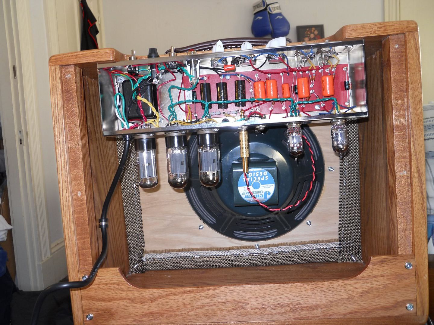
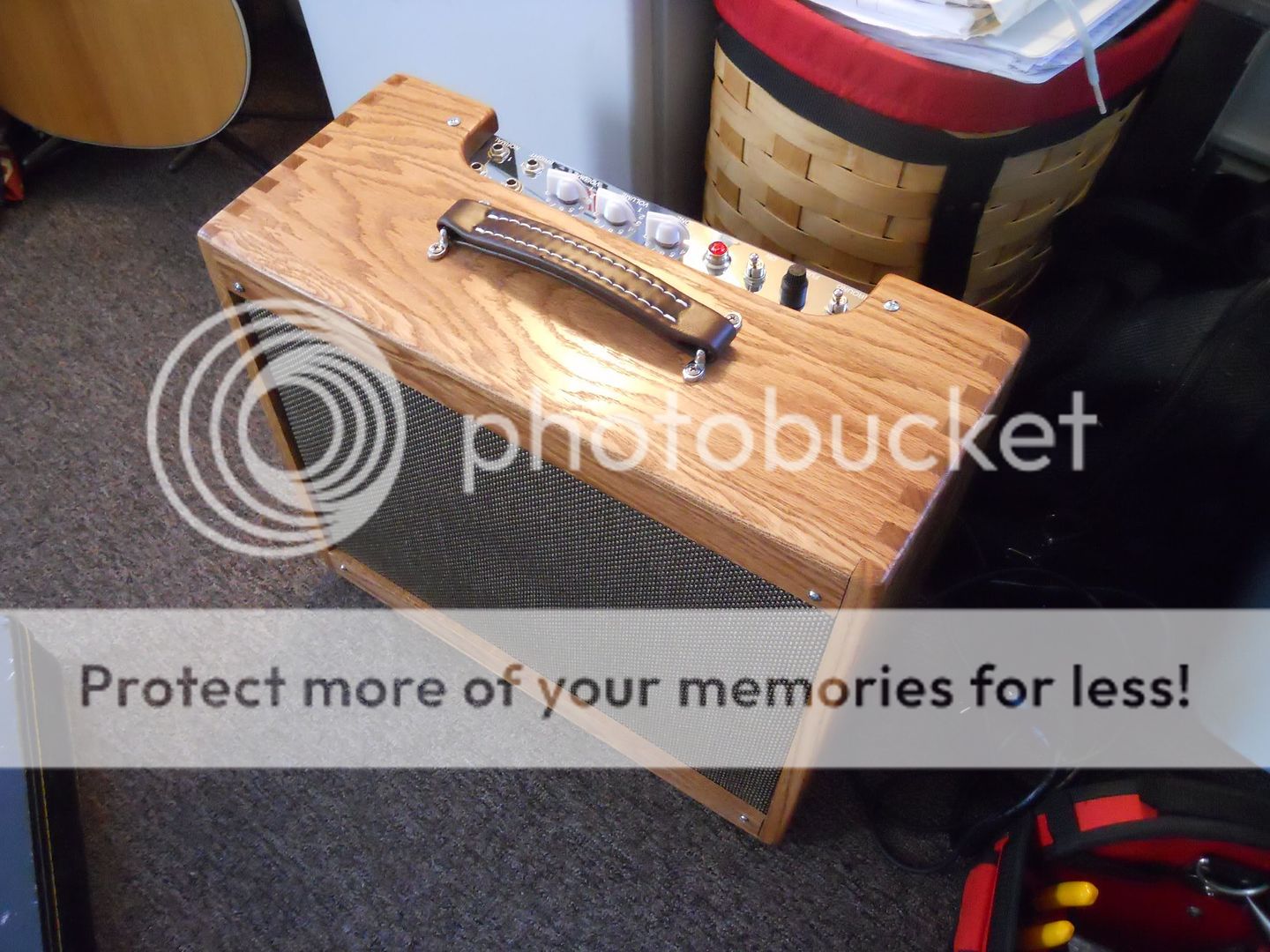
I recently built a modified 1957 Fender Deluxe tube amp. Even built the cabinet by hand.
For my senior project I'm working on a simple 3-Band Equalizer for the Amp. My design has to meet these specifications.
• The Equalizer Pedal will be powered using a 9V battery
• A push button will turn the foot pedal on and off
• A minimum 3-band equalizer will be designed
• Low (Bass) center frequency band: 78Hz (5% tolerance)
• Middle center frequency band: 1.15kHz (2% tolerance)
• High (Treble) center frequency band: 7.8kHz (2% tolerance)
• At least +/- 15dB per band
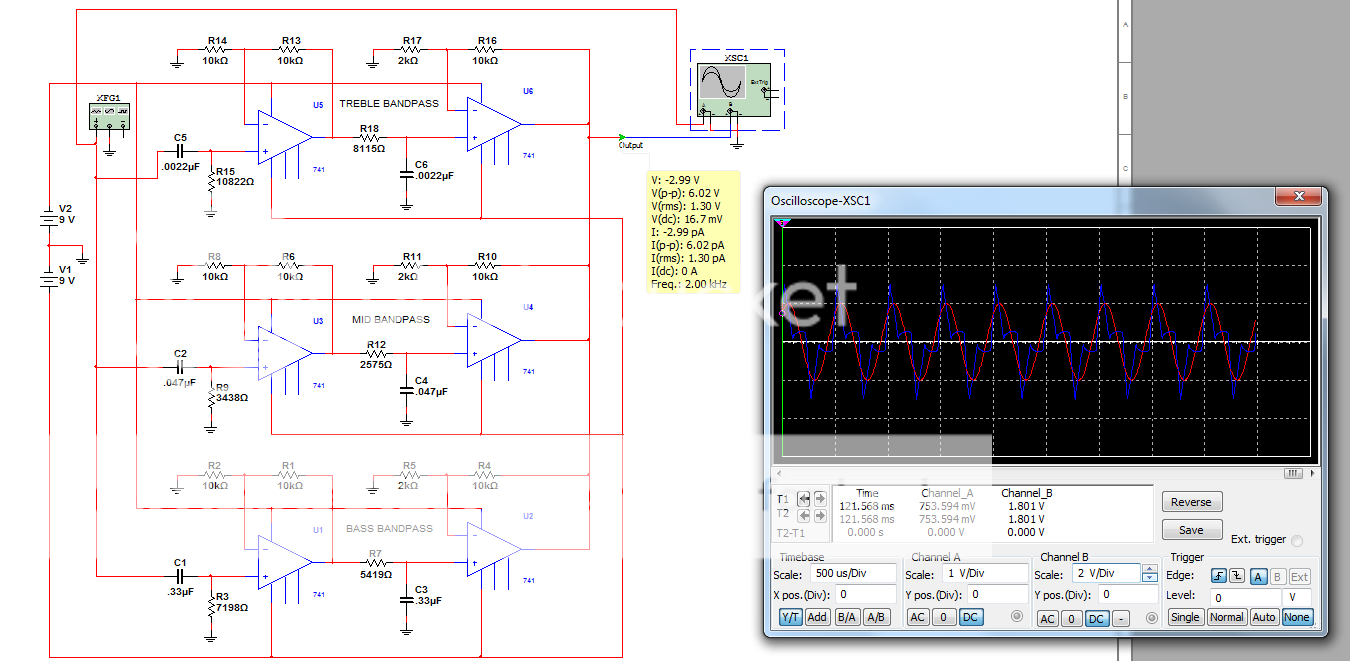
Above is what I have so far. 3 simple band pass op amp circuits with some extra resistors to set the gain. I have the push button switch wired, just not shown. I'm running into problems getting the gain I want, frequencies not matching what I want on bode plot, and I'm not sure how I'm going to use potentiometers to create +/- 15dB per band.
Any and all help will be much appreciated. Getting pretty stressed out over this.
For my senior project I'm working on a simple 3-Band Equalizer for the Amp. My design has to meet these specifications.
• The Equalizer Pedal will be powered using a 9V battery
• A push button will turn the foot pedal on and off
• A minimum 3-band equalizer will be designed
• Low (Bass) center frequency band: 78Hz (5% tolerance)
• Middle center frequency band: 1.15kHz (2% tolerance)
• High (Treble) center frequency band: 7.8kHz (2% tolerance)
• At least +/- 15dB per band
Above is what I have so far. 3 simple band pass op amp circuits with some extra resistors to set the gain. I have the push button switch wired, just not shown. I'm running into problems getting the gain I want, frequencies not matching what I want on bode plot, and I'm not sure how I'm going to use potentiometers to create +/- 15dB per band.
Any and all help will be much appreciated. Getting pretty stressed out over this.
Nice woodwork Joshwa! May I suggest you find a way to hold the tubes in place, they are way to expensive to loose!
About your circuit (we've been there before!), it will not do what you want it to do. You have 3 BP filers that, on a frequency sweep, will give you 3 adjustable bumps. Go to http://www.all-electric.com/schematic/mix-eq.htm and simulate or build the circuit on the bottom left. E
PS: You should also have a combining network (fancy term for 3 resistors) on the output of the ICs in your circuit before the signal goes to the next stage. R values depend on the output impedance of the ICs and the load. E
Last edited:
Thank you for the complement and helpful information Mickey. =)
I've tried circuits 2 & 5 before. I can't calculate +/- 15 db of gain using the gyrator circuit (circuit 2). Correct me if I'm wrong but circuit 5 looks like a modified baxandall circuit in which calculating the mid frequency and gain becomes very complex because it relys on the bass and treble values.
I figured I'd try to design as simple of a circuit as possible to meet my specifications.
- Status
- Not open for further replies.