How many times you need to be told that 3k5 OPT with 400 V +Ub is fully OK for a GU50 triode connected pair?
Dear Mona,
We are talking about the output stage.
But your coment is welcome and relevant.
I have seen many schematics with drivers.It seems there is a good reason.
It's seems that the best who can be do is -40vThat's no good.
The bias needs to be -50V or more (GU50,triode,400V), demands to much drive for the concertina.
And with the right drive only somewhat over 20W out.
Mona
For the drivers here is something better:

Last edited:
It seems to me we're going 'round and 'round in circles because some crucial design decisions are not being made.
You already have push-pull output transformers, which are capable of 50W or more output and have 3.5k plate-to-plate primary impedance. Your output stage will have to be push-pull, and it will have to run well with that low-ish primary impedance.
1) The first step is to choose the output tubes and decide whether you want triode or ultralinear or pentode operation, and then decide whether you want class A, class AB1 or class AB2 operation.
- How much power is needed? 50 watts per channel? Really? That is a *lot* for a tube amp. If that's what is required, then you'll likely want to use pentodes in class AB, which will require a goodly amount of negative feedback applied.
NFB will be needed to reduce distortion from the output stage, because a class AB pentode output stage is going to make more 3rd and 5th order harmonics than would a class A triode output stage. The NFB 'takes the edge off' (reduces harmonic and intermodulation distortions).
NFB will also be needed to lower the output impedance of the amp. That's necessary because a pentode output stage is going to have far too high of an output impedance to work well with today's 4, 6 or 8 ohm speakers. Generally speaking, the lower the output impedance of your output stage the better. Of course there are limitations to what you can achieve. Applying lots of negative feedback invites oscillation and instability, for which you will need to apply compensation circuitry. Working with pentodes is usually more complex than working with triodes, which stay more linear with less negative feedback applied as long as the (triode) amplifier is properly designed.
EL86 would be a good tube to use in pentode mode. It's not expensive and it can make quite a lot of power for its size (it's a 9-pin miniature, about the same size and shape as an EL84).
- Do your 3.5k OPTs have screen taps (ultralinear taps) on the primaries? If so you could go with an ultralinear output stage. That's more triode-like than a pure pentode output stage, so should require less NFB, which would simplify your design. I think a pair of ultralinear EL86 in class A or class AB1 operation would work well with a 250V Ebb. The screen grids should be able to withstand 250V well enough.
- But if you only really need 10W to maybe 15W per channel, there are so many more good possibilities. You could use a pair of big triodes (like a pair of 2A3s or a pair of fairly big sweep tubes in triode with 250 to 300V plate+screen to cathode voltage). Or you could use a pair of GU50 in triode and apply negative feedback to get it to sound clean enough (necessary because of the low 3.5k primary impedance of your OPTs).
2) Once you have the output stage figured out, the next step is to design the driver and phase splitting stage. A pair of EL86 used as pentodes or run ultralinear could be driven by a classic 'cathodyne' (aka 'split load phase inverter') driver/phase splitter. The 6F12P should work for this (Russian high gain pentode-triode in one 9-pin mini envelope). You could also use a pentode as your input stage and a separate triode or even a MOSFET for the phase splitter, to make sure you end up with enough gain to add feedback despite the low Ebb.
3) You'll then need to figure out your negative feedback strategy. The most common way to apply NFB is to run signal from the 16 ohm secondary tap of the OPT to the cathode of the input tube of the driver stages. A series resistor in the feedback loop forms a voltage divider with the cathode resistor of the input tube. You choose the ratio of resistance values to adjust the level of negative feedback applied.
NOTE: If you're OK with lower power, you can go with push-pull triodes in class A and get away without negative feedback, which is easier to design. I suspect that's one reason why class A triode output stages are popular. They are a lot easier to design and build with success.
4) After you've decided on all that, now you'll need to design the power supply that will feed voltage and current to the audio circuits. Obviously if you choose the biggest, most power hungry tubes in your audio circuit you will need to buy bigger, more expensive power supply parts to support them (bigger power transformer(s), higher voltage rated capacitors, higher wattage rated resistors, etc.).
So first things first. How much power do your REALLY need to drive your speakers? 50 watts per channel? 25 watts? 15 watts? 10 watts?
Have you seen this?
A Test. How much Voltage (power) do your speakers need?
I found that with my 91dB/1W speakers I really only need 10W per channel to play music loud enough to annoy the neighbors. But I live in an apartment complex, so it's pretty easy for my neighbors to hear music playing from my apartment. So I did just fine with a measly 6W per channel from push-pull class A 2A3s. Only six watts. 50 watts per channel would be nice for me, I suppose, but not necessary.
So really, if you want to get anywhere with this, you'll want to make those decisions before you start purchasing parts for the project. If you're on a budget, first decided on a good plan so you can choose your parts wisely.
Good luck.
--
![IMG_4447[1].JPG](/community/data/attachments/807/807708-0bee85d35c4f5a2817a0d6a4f4446a16.jpg?hash=C-6F01xPWi)
If you must have 50 watts per channel, then there are three classic driver stage/phase splitter topologies you can choose from that stand a ghost of a chance of being able to drive big output tubes from only a 250V to 300V Ebb:
1) "Williamson" driver - Uses a common cathode triode into a concertina/cathodyne phase splitter, which feeds the push-pull signal to a differential pair of triodes, which then drives the push-pull pair of output tubes. You can get a lot of gain from this kind of driver circuit, but it has a lot of stages, so you can't apply great gobs of NFB without it oscillating or becoming unstable in some way. If you need a lot of signal drive with limited power supply volts then the Williamson driver is probably the best way to go.
2) "Mullard" driver - This uses a single triode common cathode amplifier stage to drive the input of a long-tailed pair (LTP)/cathode coupled amplifier phase splitter. That LTP stage drives the push-pull output tubes. The common cathode stage is usually DC-coupled to the LTP stage, but that probably won't be possible with only a 250V to 300V Ebb.
This type of driver circuit has only three stages including the output stage, so can accept more NFB than the Williamson can before becoming unstable or oscillating. However, it is usually less linear (distorts more) than the Williamson driver circuit, so the Mullard driver will likely need more NFB to achieve as low distortion performance. (Nothing's perfect. Everything is a compromise between this and that.)
3) "Dual Differential" driver - This one uses two push-pull (differential) twin-triode stages to drive the push-pull output stage. The first stage is a long-tail pair of identical triodes, which will require a negative supply for a constant current sink (CCS) in series with the LTP cathodes (the 'tail') to achieve good push-pull balance for low distortion.
That first LTP stage is usually DC-coupled to a second differential pair of triodes, which then drive the output stage. However, with only a 250V to 300V Ebb, the DC coupling may not be possible. That would mean you'd need to use TWO constant current sinks per channel, one for each of the differential pairs (per channel).
This Dual-Diff driver can work very well indeed, but is more complex to set up than the Williamson or Mullard drivers.
...And that's just the driver stage.
--
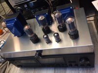
My 13 W PP 6P3S with speakers Electro-voice 92 dB. And sound is very very loud. /I made my speakers - I changed Jensen 12" to full range El-Voice/. In your decision you never will use 2 x 50 W.
What output transformers are you using with your 6P3S tubes to get your 13W per channel? What is their primary impedance?
Are you running those 6P3S in triode or in ultralinear?
How many volts is your B+?
My guess is your B+ is 400V, you're running the 6P3S in push-pull triode, and the OPTs' primary impedance is 6.6k or 7.6k or maybe 8k ohms.
Am I close? (Maybe I'm wrong, but it's fun to guess...)
--
Last edited:
azazello,
Nice looking amplifier.
Nice efficient speaker.
=
Nice sound!
The 12 inch EV Wolverine was my first speaker. Mono. 1959. A fun start to the journey.
If you have the time, it would be nice to see the schematic of your amplifier.
Thanks!
Nice looking amplifier.
Nice efficient speaker.
=
Nice sound!
The 12 inch EV Wolverine was my first speaker. Mono. 1959. A fun start to the journey.
If you have the time, it would be nice to see the schematic of your amplifier.
Thanks!
Last edited:
I used EDCOR UL OT - 7... konm. Power transf. with 260-270 V- I forgot. Bridge full w. rect. I make amps without schems, they are in my head, and after 1 year I forgot them. Sorry. Speakers are cool /30-13000 Hz and tweeter for 20000 Hz, middle are disconnected/. These speakers are better, than speakers for some thousand $. Its very easy to build..
/SORRY FOR OFF/.
IMO, if compare GU and 2A3,....Gu50 is bad tube with big power..... 2A3 is the best tube for sounding. But You will decide.
/SORRY FOR OFF/.
IMO, if compare GU and 2A3,....Gu50 is bad tube with big power..... 2A3 is the best tube for sounding. But You will decide.
Last edited:
It seems to me we're going 'round and 'round in circles because some crucial design decisions are not being made.
You already have push-pull output transformers, which are capable of 50W or more output and have 3.5k plate-to-plate primary impedance. Your output stage will have to be push-pull, and it will have to run well with that low-ish primary impedance.
1) The first step is to choose the output tubes and decide whether you want triode or ultralinear or pentode operation, and then decide whether you want class A, class AB1 or class AB2 operation.
- How much power is needed? 50 watts per channel? Really? That is a *lot* for a tube amp. If that's what is required, then you'll likely want to use pentodes in class AB, which will require a goodly amount of negative feedback applied.
NFB will be needed to reduce distortion from the output stage, because a class AB pentode output stage is going to make more 3rd and 5th order harmonics than would a class A triode output stage. The NFB 'takes the edge off' (reduces harmonic and intermodulation distortions).
NFB will also be needed to lower the output impedance of the amp. That's necessary because a pentode output stage is going to have far too high of an output impedance to work well with today's 4, 6 or 8 ohm speakers. Generally speaking, the lower the output impedance of your output stage the better. Of course there are limitations to what you can achieve. Applying lots of negative feedback invites oscillation and instability, for which you will need to apply compensation circuitry. Working with pentodes is usually more complex than working with triodes, which stay more linear with less negative feedback applied as long as the (triode) amplifier is properly designed.
EL86 would be a good tube to use in pentode mode. It's not expensive and it can make quite a lot of power for its size (it's a 9-pin miniature, about the same size and shape as an EL84).
- Do your 3.5k OPTs have screen taps (ultralinear taps) on the primaries? If so you could go with an ultralinear output stage. That's more triode-like than a pure pentode output stage, so should require less NFB, which would simplify your design. I think a pair of ultralinear EL86 in class A or class AB1 operation would work well with a 250V Ebb. The screen grids should be able to withstand 250V well enough.
- But if you only really need 10W to maybe 15W per channel, there are so many more good possibilities. You could use a pair of big triodes (like a pair of 2A3s or a pair of fairly big sweep tubes in triode with 250 to 300V plate+screen to cathode voltage). Or you could use a pair of GU50 in triode and apply negative feedback to get it to sound clean enough (necessary because of the low 3.5k primary impedance of your OPTs).
2) Once you have the output stage figured out, the next step is to design the driver and phase splitting stage. A pair of EL86 used as pentodes or run ultralinear could be driven by a classic 'cathodyne' (aka 'split load phase inverter') driver/phase splitter. The 6F12P should work for this (Russian high gain pentode-triode in one 9-pin mini envelope). You could also use a pentode as your input stage and a separate triode or even a MOSFET for the phase splitter, to make sure you end up with enough gain to add feedback despite the low Ebb.
3) You'll then need to figure out your negative feedback strategy. The most common way to apply NFB is to run signal from the 16 ohm secondary tap of the OPT to the cathode of the input tube of the driver stages. A series resistor in the feedback loop forms a voltage divider with the cathode resistor of the input tube. You choose the ratio of resistance values to adjust the level of negative feedback applied.
NOTE: If you're OK with lower power, you can go with push-pull triodes in class A and get away without negative feedback, which is easier to design. I suspect that's one reason why class A triode output stages are popular. They are a lot easier to design and build with success.
4) After you've decided on all that, now you'll need to design the power supply that will feed voltage and current to the audio circuits. Obviously if you choose the biggest, most power hungry tubes in your audio circuit you will need to buy bigger, more expensive power supply parts to support them (bigger power transformer(s), higher voltage rated capacitors, higher wattage rated resistors, etc.).
So first things first. How much power do your REALLY need to drive your speakers? 50 watts per channel? 25 watts? 15 watts? 10 watts?
Have you seen this?
A Test. How much Voltage (power) do your speakers need?
I found that with my 91dB/1W speakers I really only need 10W per channel to play music loud enough to annoy the neighbors. But I live in an apartment complex, so it's pretty easy for my neighbors to hear music playing from my apartment. So I did just fine with a measly 6W per channel from push-pull class A 2A3s. Only six watts. 50 watts per channel would be nice for me, I suppose, but not necessary.
So really, if you want to get anywhere with this, you'll want to make those decisions before you start purchasing parts for the project. If you're on a budget, first decided on a good plan so you can choose your parts wisely.
Good luck.
--
Hello,
Thanks a lot for your pain:
You spended a lot of time to write to explain how i must do.
My choice go to a Gu50 push-pull triode mode feeded at 420v.
As Mona as written Opt (vg=-20v) is not good (-40v should be better)
I don't need 50w output power per chanel :the area of my living room is 20m^2.
I will use 6n8s for drivers and phase spliter.
Two possibility for me:
1) Williamson Stancord like:
Amplifier, concertina phase spliter and drivers :
High gain but until 3 phase inversions
2)Long tail pair inverter and drivers :
Lower gain but 2 phase inversions at maximum and seems better as first.
In the two cases it needs only two tubes.
Perhaps i will add a buffer at the entrance(cathode follower).
The TME power transformer looks good.
For a few more than 100€ i will order a pair
The voltage will be regulated with a zenner and a transistor.
I have stainless steel sheets.
I will build two mono blocks.
For 6f12p i know this good tube :i builded early a phono preamp with it.
Last edited:
Hello,I used EDCOR UL OT - 7... konm. Power transf. with 260-270 V- I forgot. Bridge full w. rect. I make amps without schems, they are in my head, and after 1 year I forgot them. Sorry. Speakers are cool /30-13000 Hz and tweeter for 20000 Hz, middle are disconnected/. These speakers are better, than speakers for some thousand $. Its very easy to build..
/SORRY FOR OFF/.
IMO, if compare GU and 2A3,....Gu50 is bad tube with big power..... 2A3 is the best tube for sounding. But You will decide.
GU50 for me 23A is too expensive for me, even 6s4s.
You might also opt for the cheap EL36/6CM5/6P31S sweep tube or it's even cheaper 300 mA/25 V series heated variant, the PL36/25E5. A pair of them is good for more than 40 watts at Ebb = 300 V, Escr = 150 V, Zpp = 3k5. And it is easy to drive, as it only requires a swing of 20 Vpp per grid for full power.
Best regards!
Best regards!
- Home
- Amplifiers
- Tubes / Valves
- 3,5kΩ 50w push-pull transformer.