Hi
I use the pair 3sj103&2sk246 in the F5:
When I tray to bias , the 2sj103 bios normally, when I clock count the pot the current rise.
But when I try to bias the 2sk246 the max is 0.2A when the 2sj103 gives 1A.
I have many of this transistor and after replace the results is same.
thanks
I use the pair 3sj103&2sk246 in the F5:
When I tray to bias , the 2sj103 bios normally, when I clock count the pot the current rise.
But when I try to bias the 2sk246 the max is 0.2A when the 2sj103 gives 1A.
I have many of this transistor and after replace the results is same.
thanks
Last edited:
It's best you approach these thing systematically.
Use the same dc supply voltage as shown in the f5 article.
Then measure important voltages eg Vgs etc and put them on this thread.
Others who take picture and use schematics with measured voltages written on the diagram tend to get quite a lot of help.
Use the same dc supply voltage as shown in the f5 article.
Then measure important voltages eg Vgs etc and put them on this thread.
Others who take picture and use schematics with measured voltages written on the diagram tend to get quite a lot of help.
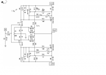
set both P1 and P2 to zero - confirm same measuring ZERO OHMS across R5 and R6
change R5 and R6 to 4K7
start biasing procedure - plenty of tutorials ( member 6L6 and others ) around
change R5 and R6 to 4K7
start biasing procedure - plenty of tutorials ( member 6L6 and others ) around
EDIT: (Deleted potentially confusing part of my post)
EDIT: Re-reading your initial post, it sounds like you have a problem with the front end.
Before biasing the output stage, set the P1 and P2 to zero ohms as ZM suggests and P3 set to the midpoint. With no power applied, the resistance measured across R3 and R4 will be the same and slightly below 10R if the pot is centered. Then apply power and measure the voltages across R3 and R4. They should be the same, or at least very close. If not, figure out why. If they are close, then you can proceed to biasing the output stage.
Last edited:
please - do not confuse him more
fact is that he can't open output mosfets with wimpy Idss , which his input Jfets certainly have
first thing first , later more complicated
fact is that he can't open output mosfets with wimpy Idss , which his input Jfets certainly have
first thing first , later more complicated
Hi
ZM is right.
I do a lot of time the biasing procedure, but now the 2sk246 do not change the current, just little.
When I switch to the original pair: 2sk170 the F5 work fine and the currant is equal.
After change the resistor I post the results.
Thanks a lot
ZM is right.
I do a lot of time the biasing procedure, but now the 2sk246 do not change the current, just little.
When I switch to the original pair: 2sk170 the F5 work fine and the currant is equal.
After change the resistor I post the results.
Thanks a lot
Last edited:
smart to point that 
I'm always so hysteric about pinouts , so I'm forgetting that other ppl maybe aren't
erez
just search for datasheets and you'll see
I'm always so hysteric about pinouts , so I'm forgetting that other ppl maybe aren't
erez
just search for datasheets and you'll see
170's are supposedly "short channel devices" which means you can swap the D-S, S-D...
Just sayin 😀
Just sayin 😀
I tried that out of curiosity and got 50% greater Idss when reversed. The opposite of erez's problem.
I too have measured a very few sk170 and compared Idss with DS swapped and conventional.I tried that out of curiosity and got 50% greater Idss when reversed. The opposite of erez's problem.
As far as I can tell the jFET does not appear to be damaged by swapping D&S for Idss checking. It reverts to standard Idss.
Usually the reversed Idss is a couple of percent lower. I have never found any that are more than 5% lower when reversed. Some measure the same in both directions.
- Status
- Not open for further replies.
- Home
- Amplifiers
- Pass Labs
- 2sk246 bias problem