greetings,
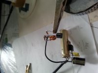
1. 2SK170GR from japan Idss 5.63ma with 7809 regulated voltage applied with gate source shorted to earth
2. rigged two C batteries for max -3vdc negative biasing adjustable via 3/4watt 1M Bjorn ten turn trimmer set midway. Bjorn trimmer wiper fed to gate, -3vdc (upsidedown) battery earth connected to source. -3/2vdc negative gate must be applied before applying tension in next step. use dvm to confirm presence negative gate voltage applied
3. 7809 regulated power applied to drain (+) and source (-) with ammeter view active. there is no feed resistor! fluke ammeter directly measures Id
4. Id won't flow yet, excessively negative biased (-1.5vdc) gate wrt source
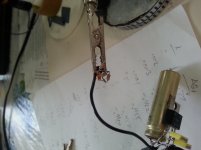
5. dial Bjorn trimmer to initiate Id flow (threshold) is the pinch characteristic. record negative pinch gate voltage for threshold Id~~zero
6. dial Bjorn trimmer incrementally recording corresponding applied negative gate voltage versus fluke ammeter Id
7. eventually Bjorn trimmer maneuvered into minuscule negative gate voltage causing Id asymptotic approach to Idss
8. attached data record of findings. looks like Rs is calculated by graphing the ordered pairs, trashing the nonlinear portion, least squares line fitting the linear portion. the line slope is the resistor value of Rs with Y-axis as negative gate bias volts and X-axis as Id. But Rs came out 7.9 ohms!
9. please help, something is not correct here, properly biasing the 2SK170GR as a buffer with 7809 power, desired 1M guitar input impedance, desired line level output impedance, desired guitar frequency spectrum
1. 2SK170GR from japan Idss 5.63ma with 7809 regulated voltage applied with gate source shorted to earth
2. rigged two C batteries for max -3vdc negative biasing adjustable via 3/4watt 1M Bjorn ten turn trimmer set midway. Bjorn trimmer wiper fed to gate, -3vdc (upsidedown) battery earth connected to source. -3/2vdc negative gate must be applied before applying tension in next step. use dvm to confirm presence negative gate voltage applied
3. 7809 regulated power applied to drain (+) and source (-) with ammeter view active. there is no feed resistor! fluke ammeter directly measures Id
4. Id won't flow yet, excessively negative biased (-1.5vdc) gate wrt source
5. dial Bjorn trimmer to initiate Id flow (threshold) is the pinch characteristic. record negative pinch gate voltage for threshold Id~~zero
6. dial Bjorn trimmer incrementally recording corresponding applied negative gate voltage versus fluke ammeter Id
7. eventually Bjorn trimmer maneuvered into minuscule negative gate voltage causing Id asymptotic approach to Idss
8. attached data record of findings. looks like Rs is calculated by graphing the ordered pairs, trashing the nonlinear portion, least squares line fitting the linear portion. the line slope is the resistor value of Rs with Y-axis as negative gate bias volts and X-axis as Id. But Rs came out 7.9 ohms!
9. please help, something is not correct here, properly biasing the 2SK170GR as a buffer with 7809 power, desired 1M guitar input impedance, desired line level output impedance, desired guitar frequency spectrum
Attachments
> confirm presence negative gate voltage
When making test rigs, "always" put some resistance in there, so an accident does not blow-up the device being tested. Reverse (normal) gate resistance is "infinite", so you can use a very large resistor. You want low enough that meter-loading is insignificant (so 100K for a 10Meg meter) and high enough so no handy voltage can exceed the 10mA gate current rating (so 1K). 10K seems fine.
> power applied to drain ... there is no feed resistor!
I would put some resistance in there, to save me from my mistakes. 1K is very safe but will cause big Vds errors at 6mA. Worst-case with resistor and 9V supply is at 4.5V. 0.4W dissipation rating on FET. (4.5^)/0.4 says 51 Ohms is safe, 100 is safer and will still be small error at 6mA.
> threshold Id~~zero
What is "~~zero"? Micro-Amps? Nano-Amps? Femto-Amps? Current can be incredibly small, there is no "zero".
Toshiba takes the reasonable value of 0.1uA as "cutoff" for data purposes, because that is as small as can be measured without specialized equipment.
Your data says 0.1uA is somewhere below -0.5V, which is in-the-middle of the specified 0.2V-1.5V range.
> eventually Bjorn trimmer maneuvered into minuscule negative gate voltage causing Id asymptotic approach to Idss
You knew from datasheet you should only need 1.5V to get "off", so starting from 3V makes it trickier. A quick turn would show more like 0.5V, so I would use a 10K pot and 10K or 15K in series to spread-out the desired 0V-0.5V range.
> graphing the ordered pairs, trashing the nonlinear portion
The meaning of "mV/mA" is not clear. It is of course static (not incremental) Gm, but I don't see how that helps initial bias.
And the curve is nonlinear ALL the way.
> properly biasing the 2SK170GR as a buffer
Not sure what your goal is. To bias one specific 5.6mA FET to "half" of Idss?
You can't do that in production.
We almost never need more than around 1mA in small-signal audio stages.
JFETs can have rising hiss at low current. Some study of good FETs and the thermal hiss of an electric guitar says we may never hear JFET hiss. However the '170's hiss rises below ~~1.5mA, so let us use 1.5mA.
Interpolating your data, for the specific part in your hand, you need -0.177V to be near 1.5mA. 0.177/0.001,5 is 118 Ohms for RS.
To set the Drain near half of 9V, we need 4.5V drop, at 1.5mA, is a 3K Drain resistor.
Input and output bias and coupling should be added.
Is 3K OK? Well, guitar-cord loads tend to be 50K and higher, so 3K is exceptionally low. This is also the output impedance. If 3K is loaded with 3,700pFd (123 feet or 37 meters of typical cable) response will be -3dB at 15KHz, -1dB at 7KHz, which is just good enough for great guitar. If you need longer lines, I suggest a push-pull circuit (so probably a chip).
BUT. What is the gain and the overload? Squinting your numbers, incremental Gm at 1.5mA is about 17mS, or like a 57 Ohm added resistor. So 175 total Ohms in Source. Almost 3K in Drain. Gain is like 16. (You "never" want that much gain between guitar-cord devices.) Maximum output swing is not even 4V peak. Maximum input is less than 0.25V peak (we could have guessed from the 0.5V total swing at Gate). Maximum RMS input is 180mV. This is a medium guitar signal. Many hard strums will exceed this and go "splatt".
You really do not want gain over 3 from guitar to 9V amplifier.
The simple hack is to AC-couple the grid (with a cap), cut-up the 3K and put 1K in Source, 2K in Drain. The 1K goes under the 118-100r bias, the gate resistor returns to this junction. Gain is now 2, mav input near 1V peak. Also the distortion which may have been 5%-10% THD at clipping is now near 1%.
Or put all 3K in Source. Unity gain. While you could keep a 118r bias resistor, it is really simpler and much more device-tolerant to use a bias-splitter to set the Gate near 4.5V. Then "any" device with Idss>3mA and Vto<1V will drop-in and work good.
Attachments
Ok thank you for steering bias to the middle area over the whole gate voltage differential spectrum, from your illustration my slope resides way up in your region of curve where behaviour is straight line, go look closely at this region. That's why I arbitrarily selected that preferential regime of predictable behaviour.
Yet you're saying setup bias prototype to feed low pico guitar cabling into guitar amp, abstain from sound engineer unreceptive input impedance.
Will redo data pairs all over again with your higher resolution reveal approach on both meters (watch negative bias volts, watch 7809 power milliamps) although your insertion of lowered resistivity aiding resolution might affect the actual measurement desired (skewed measurement?). I recall scanning electron microscope magnification pots dialed were twenty turn, made in germany. Boy I sure would like one, then the loading would be insignificant to measurement. Else I would rig up a non-battery 1.5 negative dc supply which could steadfast support your increased loading the two C's capacity wouldn't. Measurements stability and repeatability and noise induced by greater currents is concern. Aerial antenna crosstalk conductor exposure another concern. All leads under six inch length includes multimeters. Power has to be clean.
Now about this japan jfet. Run it hot! But don't kill it. Is it legal, 5.63ma idling? You arbitrarily opted for coolzone 1.6ma? the luscious sound is unleashed esp with exaggerated readiness tension. Some say lowered tension is more even order harmonics as in tubes. But the real test is to listen. Now that sounds counterproductive, run it hot as in catchfire vox ac30!
But if it can be accomplished, this "run it hot" biasing, and if it can be bulletproof, then hooray we have what the players desire. My personal plan is to feed that circuit "lilttle gem mark ii" that incorporates a buffer but it's a junk buffer compared to what I am shooting for. The gem drives an old cigar box housing twin power macintosh oval three inch full range paper speakers. Small box but heavy timber gauge used back in the fifties. Gem is sized half stick Wrigley' s chewing gum stick! Japan fet can be accommodated into halfstick. This way, two user ports on box, coaxial power input, and standard guitar jack. No dials! There's a "super version" of this gem sporting tone stack and volume, but another 2SK170GR is necessary for throw-away energies reboost recover.
Masterplan is clear, no scrimping battery longevity phobia! Run that japan jfet sizzling hot that's what shines out its inherent character! Another inquire is that of the little gem, can piggyback 386 dip be applied twice onto little gem? Gem is already built sporting two 386 but absent buffer. What does piggybacking accomplish? You'd think parallel is cluster power for the gem already is in push pull mode, parallelling additional 386 tightens the output? as in compliant?
the 2SK170 and 1/2 Idss bias seem a poor match to magnetic guitar pickups typical high kOhm Rdc and even higer inductive Z over audio
you pay for unneeded low e_n with freqency response changing input C, total noise degrading i_n
you pay for unneeded low e_n with freqency response changing input C, total noise degrading i_n
Last edited:
> Is it legal, 5.63ma idling?
Yes. Round-numbers, 6mA and 9V is 0.054 Watts, far less than the 0.4 Watt rating.
BUT 5.63mA is very-nearly the MOST current it will pass. It looks like you might get 6mA maybe 7mA before the forward-bias Gate loads-down your signal (distorts bad).
"Generally" you pick a FET with Idss at least twice the selected idle current. Then it can swing from idle to zero to 2X idle, both ways. Only if signals are very-very small (radio antenna) can you idle near Idss without gross distortion.
With the rather high levels off a guitar pickup, _I_ would start by picking a Vto range greater than the peak-to-peak signal level, or plan on other circuit techniques to make it linear for large signals.
> the luscious sound is unleashed esp with exaggerated readiness tension.
So do it. It is not a real expensive experiment. See how it sounds.
Chose 2sk170gr for piezo transducer project for acoustic guitar and indeed battery longevity was concern, but fortunately driving hi z input of guitar amp, conversion into church mixer required impedance transformer (lowers impedance to sound engr). So yes piezo is capacitive transducer just like tube and fet microphones sporting the piezo element of capacitance.
So wrong choice 2sk170gr for tele stnd pups? That's about five to six kilo ohms dc, dunno their stock inductances, signal unloaded fluke measures true rms roughly under twentyfive ac mv, and can escalate to twice that on intentful attack, but that's tiny compared to same of piezo whose ma is ziltch.
Confused on your explanation that performance is rubber banded spring return, wanton desired suffers unwanton ills! Can you please explain? I really am infatuated to that luscious sound, it is so pleasing you don't put the tele down, so the band keeps on playing even longer.
2sk170gr intended for moving cartridge phonograph transducer 1st stage or initial stage eq so it is for signals significantly tinier than telecaster stock pickups?
resistor source at 3.6k at source voltage 4.67 of gate 4.17 of drain voltage 9
resistor source at 3.6k at source voltage 4.67 of gate 4.17 of drain voltage 9
1.5m drain resistor, 1.5m gate tie down resistor, unchosen signal input cap (none, danger), picture prehistoric american tantalum really good there 15uf20v.
supply 9.00, lucky regulator i suppose,
but alas, current is idling 1.32ma
so fuel flow ! shrink resistor source substantially to power orders threefold? that's kilo shrunk to hundred shrunk to ten !
and why three orders of power? why? try source resistor 360 then 36 then 3.6 !
Attachments
source current raise to 3ma from 1.3ma
okay, got it at half powering voltage on that source resistor, 4.57 volts above earth. Gate voltage remains same as before 4.16 volts above earth since both drain resistor and gate tie-down resistor are identically 1M5. i don't know why gate voltage above earth is not half powering voltage from the 7809. the craftsman pocket multimeter 82351 does not have meter connection receptacles for test leads so lead lengths are antennae long 18" each. the fluke 76 multimeter has 6" leads and measures milliampere thruput 2sk170gr. the 7809 powering voltage sags when measuring gate voltage above earth, why, because of craftsman aerial antennae leads, gotta scope the jfet's output ac signal waveform W/OUT_ANY ac 1khz nominal 5mv rms signal injected. this should reveal test leads infiltration noise extraneous? quiescent milliampere is now 3.146 as long as gate is not craftsman probed by test lead to measure gate voltage above earth. whenever gate voltage above earth is measured, milliamperes fall somewhat to steady
2.931. so obviously the 7809 power supply is being fingered for more current and it's powering voltage does sag downwards to 8.97 which is trivial but why should current fall 3.146-2.931=0.2ma? shouldn't it go the other way, upwards instead, since we're demanding noise signal injection buffering in lieu of no injected noise from craftsman test leads noise intrude? since i'm on the desk workbench open to world noise, should i coax the 7809 powering umbilical into the 2sk170gr substrate?the other bothering question is whether gate voltage is good enough at 4.16 since web literature request centering gate voltage to half of that of powering voltage, 4.5, meaning precise 1M5 resistors must be employed to achieve 4.5 gate voltage? additionally, you don't know whether the gate voltage measurement is actually erroneous owing to test lead probe intrusion into gate which has extreme sensitivity (huge antennae? 18" unshielded red test lead of pocket craftsman multimeter). must visual wave form on scope of 2sk170gr output w/ and w/o signal inject for unwanted noise infiltration. trouble is test leads noise introduction might be counterproductive by introducing test leads noise which 2sk170gr buffers.
one last report, tried source resistor 385 ohms and milliamperes soared to 11ma! immediately disengage 7809 powering. Idss (gr version) says max 6ma. so, is it ok to exceed this as in 11ma? did jfet get wounded from thruput 11ma split sec?
jfet rated at .4watts, so (i^2)*Rs=watts= .0465 watts
wait a minute how is 2sk170gr thermal dissipation wattage determined? it can't just be merely (i^2)Rs. current heats 2sk170gr, current heats Rs, current heats both 1M5 resistors trivially.
how is heat determined inside the 2sk170gr? we know current, and we know the voltage across Rs. Since powering voltage is known, the voltage across both 2sk170gr plus Rs must total powering voltage ignoring any gate node current(s). so 9.0-4.57=4.43 across 2sk170gr, heat dissipation 2sk170gr=watts=(i^2)*(R_jfet)=i*(V_jfet)=(.011)*(4.43)=.04873watts. the overall heat dissipation ignoring gate current(s) ignoring output signal dc blocking cap (yet installed) and dwnstrm tie down resistor (yet installed) heat dissipation would then be both heat dissipation wattages discussed, .0465+.04873=.09523watts. is this correct? it seems so little wattage for overall quiescent system status. this is class A amplification right? meaning power (i*v) consumed is STEADY AT MAX ALWAYS? please clarify if i am astray. thankyou.
how is heat determined inside the 2sk170gr? we know current, and we know the voltage across Rs. Since powering voltage is known, the voltage across both 2sk170gr plus Rs must total powering voltage ignoring any gate node current(s). so 9.0-4.57=4.43 across 2sk170gr, heat dissipation 2sk170gr=watts=(i^2)*(R_jfet)=i*(V_jfet)=(.011)*(4.43)=.04873watts. the overall heat dissipation ignoring gate current(s) ignoring output signal dc blocking cap (yet installed) and dwnstrm tie down resistor (yet installed) heat dissipation would then be both heat dissipation wattages discussed, .0465+.04873=.09523watts. is this correct? it seems so little wattage for overall quiescent system status. this is class A amplification right? meaning power (i*v) consumed is STEADY AT MAX ALWAYS? please clarify if i am astray. thankyou.
P = IV
when at steady state quiescent condition.
When signal flows it is no longer steady state. You would need to look at instantaneous power and average those over some time period.
when at steady state quiescent condition.
When signal flows it is no longer steady state. You would need to look at instantaneous power and average those over some time period.
Trial run
I can not center gate voltage to half powering voltage. It stays at 4.16 and appears to be dropping insignificantly as Rs is decreased to increase quiescent current toward the high end.
I don't know if the disparity is acceptable, until scoping output waveform and listening too.
Why won't gate voltage center itself with topology of an equal voltage split by the pair 1M5 resistors? The voltage across the powering gate resistor is bigger than that to the gate tie down resistor. I don't believe the pair 1M5 are mismatched to extent to cause said voltage drop inequity. Means some current got lost if more passed thru the gate powering resistor than what of it came back to earth thru gate tie down resistor. No lost conservation of current so lost current went inside the channel? I can't trimpot this locality because its the gate and its super noise susceptible with weld clutter aerial antennae. But tiniest discrete components are considerably less "antennae'y" so I've discovered, they're tinier targets to worldly noise everywhere around us. Surface mount components are the tiniest, physically. Its hard to handsolder surface mount discretely but ill try it on this gate, for dc blocking cap, 682 is rather skewed towards mix cut-through frequencies, 223 is the usual guitar, and hifi full on 1uf (105). I found some on prehistoric digital equipment elex, you gotta be clever to safely detach, thermal violation. I've discovered their pretty darn efficient insignificant losses and they behave well sound wise. Its construct is layered wafers, dunno if monolithic is the type.
i am confused whether topology "forced centered gate voltage" versus topology "none forced gate centered voltage" achieves less clutter welding. responder PRR advises a lockdown onto Rs at 3k without gate balance to achieve centered gate voltage FOR ONLY THIS PARTICULAR JFET, for unity gain. otherwise PRR suggests creating [undesired gain16] new nodal voltage tap beneath Rs=118 series connected into Rs2=2k (1k+2k mandates Rd creation, thus gain16) that is series connected to earth. this tap feeds into gate node tie down resistor mandating upstrm dc blocking cap say153. essentially it is regenerative feedback! because output input are sync'd.
my concern is which PRR topology with UNITY gain is least noise parts count w/o compromising class A reproduction irregardless of wanton jfet's coloration (tube like behavior that PRR's topologies boast marginal clarity (distort) for arbitrarily selected 1.5ma quiescence.
i don't know which way is more appealing (subjective ears?) to ears, for topologies recommended centering gate voltage. this whole 2sk170gr investigation revolves around this unity preamplification buffer. objective is to assure "class A" telecaster stock pickup signature preservation, that famous distinct clarity yet so lucratively desireable.
present circuit:
Rs=1.5k,
Rd=none,
Rg_tiedwn=1M5,
Rg_powering=1M5
Power=9vdc 1.1ampere regulated
Vg=4.16 (dunno why can't get closer to 4.5, measuring Vg somehow dips i=3.144ma)
Vs=4.57
Vd=9 (no resistor here)
power_bypass=15uf
i=3.146ma
so my (alteration), the doubling of current, from PRR's recommended arbitrarily chosen 1.5ma topology resistor values for centering source and gate, does this doubling current alteration squeeze or expand the guitar input signal pk to pk voltage range? the gain is close to unity, there is no drain resistor. guitar pup headroom is unnecessarily squeezed or enlarged by doubling current? what of freq response preferential treatment?
> Rg_tiedwn=1M5, Rg_powering=1M5
Vg=4.16 (dunno why can't get closer to 4.5, measuring Vg somehow dips i=3.144ma)
Your meter is like another 10Meg resistor gate to ground. Don't worry about it.
Yes this should be gain of 0.99 and frequency response far-far-far above the audio band and down as low as your coupling capacitors allow.
I think you are done. Play it.
Which polar side of wet axial tantalum1.5uf gets welded as dc blocking cap at gate? Gate quiescent voltage was erroneously measured 4.16vdc. But what's the comparative magnitude voltage on the upstrm side node that is telecaster? Tantalum positive side always faces the higher potential. So looking at telecaster whose transducers are earthed, whose pots are paralleled as loading. This indicates telecaster node is pure ac alone. But is positive tantalum polarity assigned toward the gate? Seems intuitively backwards, but i am not certain here. Will tie down telecaster pup node via 10pf disc cap ultrahigh freq dump. Gonna use another same wet tantalum on exit signal but here on exit tantalum polar end is clearly obvious because downstrm welded resistor 15k earth tie down.
I'm also contemplating installing sensitive gate protection though honolulu has gross atm vapor foiling static electricity accidents. So much weld prep effort went into this 3D discrete component weld matrix (optimize construct 3D volume for least noise amongst components as well as noise exposure). I don't want risk of invested effort ruin until I'm certain project is unworthy result. Adding protection might be counterproductive towards appealling sound. MOV's are used to blowout power by shorting. But are these made for wee power applications like this jfet gate? Zeners change sound.
I'm also contemplating installing sensitive gate protection though honolulu has gross atm vapor foiling static electricity accidents. So much weld prep effort went into this 3D discrete component weld matrix (optimize construct 3D volume for least noise amongst components as well as noise exposure). I don't want risk of invested effort ruin until I'm certain project is unworthy result. Adding protection might be counterproductive towards appealling sound. MOV's are used to blowout power by shorting. But are these made for wee power applications like this jfet gate? Zeners change sound.
Pics
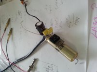
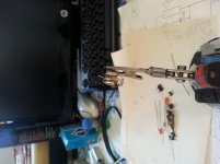
Here's the finale, still unenergized because dunno which way to orient polarized wet tantalum input dc blocking cap
Here's the finale, still unenergized because dunno which way to orient polarized wet tantalum input dc blocking cap
Attachments

> Gate quiescent voltage was erroneously measured 4.16vdc. But what's the comparative magnitude voltage on the upstrm side node that is telecaster?
Zero.
You figured the right answer. I do not know why you think it is non-intuitive.
It REALLY would make sense to breadboard or hay-wire it with low-cost parts, first, before you do your Final Build.
Zero.
You figured the right answer. I do not know why you think it is non-intuitive.
It REALLY would make sense to breadboard or hay-wire it with low-cost parts, first, before you do your Final Build.
tried that student pegboard kit thingy, it makes too much noise, even if compacting it! ahah! you believe my dc blocking wet tants value 1M5 are excessively (too much for guitar) slow pokey rise fall charge times following telecaster intrinsic signal. yes, i understand "prompt" capacitor replication of intrinsic signal, so that's why for guitar, intentional "least needed" capacitance is employed for signal passing dc blocking. yeah, maybe i am going to regret undoing those inlet exit dc blocking 1M5 caps. btw thanks for straightening me up on "polar gut feel", was actually a false positive (false negative?) ! can you contemplate a scenario whereby doom will come if an idiot erroneously inputs what? with existing and correct input tantalum polarity. some idiot on web claims an idiot would connect a source into the buffer input, so that's why the input dc blocking cap, but what the heck does that mean, a "source". does this idiot mean the signal birth from tele or a humongous speaker output 1/4" plugged in?
new concern, those european micro sized smd rectangulaoid tantalum chip, array built from multiple, cannibalized from prehistoric toshiba laptop logicboard. i checked them thoroughly for reliability but there's no markings working dc voltage. it says only 330 so it must be microfarad. it also says 84Gn and also "d" , so maybe there's a universal industry standard that says "d" means "voltage rating" ?
we do know pc's use +-12, +-5, +3.3 powering voltages. i must post a pic of the substrate created "little gem mark II" missing yet its input buffer that i must append. i have a single spare same cap and have energized it continuously by 9vdc, but that is not the same stress considering no telecaster ac signal thruput that will stress this
Tantalums come in low voltages only. The highest I have are 50V, most are 10V and 15V
330 is more likely to be nF, or pF, not uF.
I limit worst case absolute maximum voltage to <=50% of the tantalum rated voltage.
Tantalums will not tolerate reverse voltage.
If you use a tantalum as a DC block at the input and there is no voltage bias, then an input of opposite polarity is likely to damage the tantalum.
- Status
- Not open for further replies.
- Home
- Live Sound
- Instruments and Amps
- 2SK170GR buffer guitar