hi.my friend gave me 6pairs of 2sk135/2sj50 transistors.and i heard that theyre very good and low thd transistors also at low bias..does anyone have a good design?is it worth to build?
maybe not best ..... but certainly decent - designs derived directly from Hitachi ap. notes
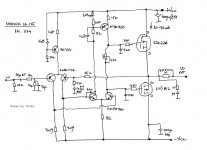
if you can't find any , I'll try to find Magnum IA125 schematic I have somewhere
if you can't find any , I'll try to find Magnum IA125 schematic I have somewhere
Hi!
Not diy brotherhood, diy Tribe!
regards zeoN_Rider
i like lateral sound.i hope you will find me a good schema. diy brotherhood
Not diy brotherhood, diy Tribe!
regards zeoN_Rider
There were a lot of amps designed around that family of transistors in the '80s. If you have access to electronics hobby magazine back issues you should find a few different designs. I don't remember any being singled out for sound quality. [An amp by H.J. Heckert, reprinted in Audio Amateur, used a bunch in parallel to do 550 watts into 4 ohms. I always thought that would be a nice subwoofer amp.] Googling with the transistor numbers and amplifier should turn something up.
On the other hand, the original transistors have been out of production a long time, so you might be better off selling them to people who need spares.
On the other hand, the original transistors have been out of production a long time, so you might be better off selling them to people who need spares.
i heard that old hitachi laterals has better sound quality than 2sk1058s.so i want to build a nice 50-75watts amp for myself.i dont want to sell them
Last edited:
Not diy brotherhood, diy Tribe!
regards zeoN_Rider
we are all sisters and brothers.came from Adam and Eve.Darwin is a lier 😎
yes its very similar to Nico Ras's RAS100 amp.i tried it it was sounding very good but suddenly burned.i didnt understand.my friend also built it and told same problem
''I've got one of these. It's a fabulous amp.
Seeing this thread, I've dug out the original WW articles, June/July/August 1982.''
''Glad you got it fired up.
I must be honest, with my cloth ears, I can't tell my JLH96 apart from my JLHMOS82.
I can tell slight differences between my JLH69 and JLH96.
I do dig it out from time to time, but have not done so for a while.''
JLH69's words about one I revived, I had it first build in the 80's. I recommend it too. Very good amp. Never burned since first build.
The pcb is roughly 125X85mm. Note Q13 is drawn in reverse in the theoretical. 2SJ50's D goes to -V in reality.
Attachments

That one I posted sports positive feedback too in an original way. Has a second reversed VAS that feeds back to the JFET tail & fb net. Also its compensation is very English. Uses a network back to the diff amp instead of an across Rf cap. Good amps all of those.

hi.my friend gave me 6pairs of 2sk135/2sj50 transistors.and i heard that theyre very good and low thd transistors also at low bias..does anyone have a good design?is it worth to build?
Here some webaddresses for lateral MOSFET schematics:
German magazine Elektor
http://www.solaris.no/electronics/power_amp/elektor_cresc/cresc_1280.gif
http://www.solaris.no/electronics/power_amp/PA105/pa105_1078.gif
http://www.audiofanatic.it/Schemi/Tipo/Stato_solido/finali/pic_finaliSS/70W_MOS_2SK135_2SJ50.jpg
http://www.amplimos.it/images/AllFETGOAPWA.gif
http://www.drtube.com/schematics/marshall/3310pwr.gif
from Shinichi Kamijo (Japan) e. g.
Non-NFB Inverted darlington 2SJ49/2SK134 150W SEPP stereo power amplifier
http://www.ne.jp/asahi/evo/amp/J49K134/zu3.pdf
and many more about
Evolve Power Amplifiers (mostly 2SJ200-2SK1529, but also lateral MOSFETs)
Tube-CAD:
http://www.tubecad.com/2006/04/01/aikido_hybrid_pp_16w_class-a_power_amplifier.png
Aikido PCBs and Aikido hybrid power amplifiers
and read this thread:
http://www.diyaudio.com/forums/tubes-valves/102613-moskido-hybrid-aikido-mosfet-amplifier.html
Now an "off topic" question from me:
I need some schematics from a brand of your country: the name is "Westsound"
please answer about this thread (address is complete mentioned), if you have informations:
http://www.diyaudio.com/forums/soli...a-600-turkish-brand-westsound-west-sound.html
http://www.diyaudio.com/forums/soli...a-600-turkish-brand-westsound-west-sound.html
Perhaps there is a pdf download aera about the websites of this manufacturer, but I don't find it. I am very happy, if you can call there to ask about the appropriate navigation advices.
hi, umut,
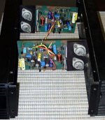
i m going to publish one i m using, mounted and working
for 15 years...since i made it a long time ago, i m currently
looking for some tweaks to check if it improve something...
the design is close to thhe one on the link, but is even more
simpler...
http://www.diyaudio.com/forums/solid-state/155993-awb50-simple-power-amp-4.html
regards, wahab
The reason isn't the circuit itself. Basicly there are parasitic effects, that causes unwanted oscillation in the aera between 1MHz and 10MHz. This means sometimes, that the highest possible power supply current flows throught the MOSFETs (e. g. 10A at 100V supply voltage), even without connected load like a loudspeaker (in this case your amp is for few seconds a high power HF transmitter).yes its very similar to Nico Ras's RAS100 amp.i tried it it was sounding very good but suddenly burned.i didnt understand.my friend also built it and told same problem
The trick is now to compensate these parasitic effects in such a way, so that the regarded amplifier may be no longer produce oscillation (also by complex load resistances) and on the other hand sonic quality does not suffer.
Even for professional developers not in all cases easy to perform independend of the circuit topology.
For this reason, "for do it yourself" such topologies to be preferred, that have relatively low values of internal open loop gain. Also helpful in some cases (unfortunately not in all cases) is the variation of the gate stopper resistor values.
Last edited:
''I've got one of these. It's a fabulous amp.
Seeing this thread, I've dug out the original WW articles, June/July/August 1982.''
''Glad you got it fired up.
I must be honest, with my cloth ears, I can't tell my JLH96 apart from my JLHMOS82.
I can tell slight differences between my JLH69 and JLH96.
I do dig it out from time to time, but have not done so for a while.''
JLH69's words about one I revived, I had it first build in the 80's. I recommend it too. Very good amp. Never burned since first build.
The pcb is roughly 125X85mm.
hello salas
i ve seen the schematic and looks very nice since i have also many of these mosftes left ( spare parts in original state from C audio amps ) i was thinking may be i built it ....
question one ....how much is the power of this amp ..... my estimation is 140W @ 8R /sine /resistive /@ 1khz ( why it say 80-100 W i dont understand ...with 60 volt rails )
question two .... is this safe enough ???? i mean only 2pairs at 60 volts ???what happens in lower loads ???
regards sakis
Last edited:
- Status
- Not open for further replies.
- Home
- Amplifiers
- Solid State
- 2sk135/2sj50 amp schematic?