I really need to build a curve tracer for BJT's and FETs. I have a USB 10ch ADC "strip chart" recorder with programmable DAC output. I just need to figure out what to measure and what to give out to the BJTs and record data trace. There are test jigs I have seen for BJTs and for FETs - would like to sort of combine somehow.
A curve tracer probably won't help confirm a good transistor.
It's probably a combination of the other parameters and seeing that all meet specifcation tolerances.
I'd start with hFE @ 10mA & 100mA, Cob @ 10Vce, fT @ 100mA
It's probably a combination of the other parameters and seeing that all meet specifcation tolerances.
I'd start with hFE @ 10mA & 100mA, Cob @ 10Vce, fT @ 100mA
A curve tracer probably won't help confirm a good transistor.
It's probably a combination of the other parameters and seeing that all meet specifcation tolerances.
I'd start with hFE @ 10mA & 100mA, Cob @ 10Vce, fT @ 100mA
Why do you think curve is not good - isn't the curve shape/resposne hard to fake?
Do you have links on how to build a test rig to measure these things? Looks complicated.
Is there a commercial transistor tester that is reasonably priced?
I know Eva described measuring AC-coupled capacitance between collector and base - and if too low, indicates a fake (small die, hence small capacitance).
I think breaking one open is the best way. Large die that is centered on thermal tab and no white RTV silicone on it.
I saw this:
Power Transistor Curve Tracer Adapter XY Oscilloscopes NPN PNP VCE 10V | eBay
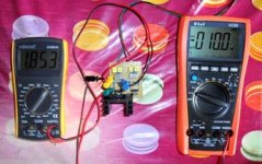
To check 2SK2013 & 2SJ313 I use this little montage (Fab Schematic) with a small program that I developed.Do you have links on how to build a test rig to measure these things? Looks complicated.
Attachments
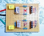

The schematic must be requested at Fab, it is part of the USSA-5 manual.Do you have a link to schematic? Looks like for FETs. Is this also applicable to BJTs?
Yes this little assembly is specific to these two references mosfet I think but should certainly be extended to other references.
If Fab does not go through here, I will contact him to ask.
If you don't like the smaller dye modern 2SC5200/A1943 it should be possible just to use the pretty recent TTA/TTC0002, they are 18A 180W devices with only slightly higher capacitances, a bit more expensive of course. I don't think they have been faked yet.
What are the disadvantages for smaller dye?If you don't like the smaller dye modern 2SC5200/A1943
thank you.
As I know, You have nothing to do with it, if You buy over 50Euro. You pay the USA VAT only, and they take care about all other costs.
Sajti
US has no VAT, but rather a "sales tax" which each individual state can levy, from 0% up to over 9% One of the reasons I turn away orders from my home state is that it costs more to fo the filings than the margin i realize on a sale!
Sanken, I believe, also made these transistors
Did you look at the test current range? It's for medium power types and only up to 500mA. You really need member Locky-z's curve tester for audio power BJTs. It has recently been uprated from the 3A test current too, I believe. Release 3 thread is linked below here and I think you can buy it finished complete on Ebay too.
There was a recent thread here, Mark Johnson's IIRC, mentioning a cased option for locky-z's tracer, which is worthwhile because I found it difficult to find a suitable case to adapt:
http://www.diyaudio.com/forums/vend...lease.html?highlight=intelligent+curve+tracer
Last edited:
What are the disadvantages for smaller dye?
thank you.
A smaller die(it is die in English not what I wrote before) means the power dissipation of the chip will be spread out over a smaller surface and the contact surface between the chip and transistor tab will be smaller making cooling more difficult. In switch mosfet transistor data sheet they sometimes have thermal impedance curves that tells you how the temperature will rise during short dissipation peaks, during really short peaks the heat sink the transistors are mounted to doesn't matter much since there is no time for the heat to transfer to the heat sink and then a larger die will take longer time to heat up.
Generally a larger die will be more robust during overload conditions, that said I have really no experience in linear amplifier design and how big a difference die size will make is not easy to tell since no audio BJT data sheet I have seen have thermal impedance curves, how much of this one can derive from the safe operating area curve is not something I can answer either.
Is there a difference in safe operating area in the data sheet of the old and new shrunk 2SC5200? Maybe someone have studied this.
Locky's curve tracer reminds me of something like a DATS impedance tester and TS parameter measurement tool for speaker building. An essential tool if you buy enough drivers and need to know (via measurement) their technical specs rather than relying on published specs. If one gets serious with amp building - a transistor curve tracer seems like a good tool as well. Getting matched transistors seems to be something that can improve performance of certain circuits.
- Status
- Not open for further replies.
- Home
- Amplifiers
- Solid State
- 2SC5200 & 2SA1943 Manufacturers