Hello fellow DIY'ers 🙂
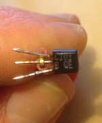
I'm fixing a transistor guitar amp for someone, and found the culprit of the problem to be an old 2SC103 transistor (base to emitter is OK; collector to base fails the diode test on my DMM).
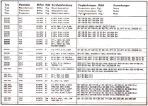
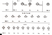
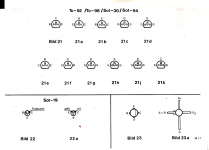
I'm having trouble finding decent info on this one (or a NOS replacement...). The only thing I found is from a page of an old Japanese reference book. (see attached image).
According to those specs; would a general NPN like a BC547 be suitable?
thanks for helping out!
Attachments
Hello Enzo,
Thank you for the reply - It's a Novanex (old Dutch amp by the looks of it) - No schematic to be found. I'll draw one up, tracing the PCB.
Looks like it's not a 2SC103 - but rather a Thyristor: C103B.
http://www.datasheetcatalog.org/datasheet/central/C103YY.pdf
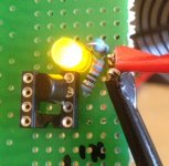
Going to check if it's allright.
Thank you for the reply - It's a Novanex (old Dutch amp by the looks of it) - No schematic to be found. I'll draw one up, tracing the PCB.
Looks like it's not a 2SC103 - but rather a Thyristor: C103B.
http://www.datasheetcatalog.org/datasheet/central/C103YY.pdf
Going to check if it's allright.
Then the thing to do is isolate the problem. In the absence of schematics, can we determine what the power supplies ought to be, or at least estimate them? Can we determine if the problem is in the power amp or the preamp?
In fact, what IS the problem you are trying to solve?
One wonders what an SCR is doing in a guitar amp.
Aha, so it is a C103B. When I looked at your photo, I almost wrote to ask if that was a 2SC1038. 8 and B look similar. But then I looked up 2SC1038 and found something not remotely like your part, so I let it drop.
Hello Enzo - the problem didn't lie with that C103 SCR - but with a BC147 near the power amp.
Here's a schematic of a different - higher rated amp (100Watt - compared to the one I have here which is 80Watt) - although it's -very- similar.
http://www.uploadarchief.net/files/download/novanex.jpg
Seems to me that SCR is being used for clipping protection? Correct?
Here's a schematic of a different - higher rated amp (100Watt - compared to the one I have here which is 80Watt) - although it's -very- similar.
http://www.uploadarchief.net/files/download/novanex.jpg
Seems to me that SCR is being used for clipping protection? Correct?
but with a BC147 near the power amp.
If that can be useful! 😀
Regards!
Attachments
Glad you found the problem.
I have not had enough sugar or coffee yet today, but I don't know that clipping would be the thing so much as over-current protection. If it were for clipping it would need to turn off after the clipped peak. But as an SCR, once curent flows through it, it stays on until current goes to zero. SO looking at the circuit, it is controlled by Q4, which is driven by the voltage sampled across the ballast resistors of the output transistors. If that gets high enough - indicating excess current through the outputs - it turns on Q4, which fires the gate of the C103, and that kills the drive current to Q9 and Q6. And that hopefully stops the outputs from conducting.
At least that is what it looks like from here.
- Status
- Not open for further replies.
- Home
- Design & Build
- Parts
- 2SC103 replacement

