Argh, I wish there were a troubleshooting forum. Not sure if this is the right place, but it seems to get more traffic than the 'Parts' forum.
I am a newb, noob, neophyte, babe in the woods, greenhorn, know nothing, worthless slug. But I am trying! Please be gentle, I promise I have the capacity to listen and learn!
My actual issue: I have 4 2SA1011 marked "A1011" "E5H3" from BD Enterprises, and another single 2SA1011 from Quest and all 5 fail the diode test on my multi-meter from collector to emitter and from emitter to collector. I've tried with two different meters (Older Wavetek 255 and a newer Tenma 72-7730). The other legs check out as I would expect (diode voltage in one direction only). I think I remember something about Germanium transistors testing strange, but the Sanyo PDF for this model makes no mention of that. I have reasons to believe this is a problem (see below), and would like to know what the group here thinks. Is this normal, or do I have great luck and 5 bad 3-legged critters? Of course, I'm overly paranoid about fakes after reading some horror stories.
Background: The 2SA1011 I am replacing is in an older Adcom GFA-555 amp that had significant damage to the left channel. I've already spent way more in tools and parts (oscilloscope, variac, meters, and dowsing rods) than it would cost to just buy a darn new amp. So I know that I am in this to learn, and not to save money. I've replaced everything that I've determined was bad (remember I know nothing...) and at any voltage up to about 50VAC the left channel is oscillating badly. But only when the 2SA1011 output board is on line. I tested all the replacement parts (new stuff only) as I put them in and the A1011 was the only part I made note of as being 'strange' when soldering away.
I've read the Adcom posts here, esp. the most excellent 'Another High DC Adcom...' post for post. This is an excellent community, with amazingly wise people. I'm still kinda dazzled that the guy who designed the original GFA-555 posts here as well.
Any help is appreciated! Thanks!
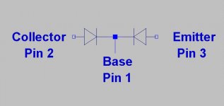
That is the way they should test, with no connection between the collector and emitter.
(see attached for the way they should test on diode check)
(see attached for the way they should test on diode check)
Attachments
Last edited:
It would be a good idea to let us know what was the original problem; did you short out the speaker terminals? Run it into a 2 ohm load, Inquiring minds need to know. Second what have you replaced and why, just because the parts were old, shorted etc.. The more back ground we have the more someone will be able to help you through this. This forum has some of the best minds (slowly aging) on the internet. I believe if you have any chance to accomplish a great repair this is the place to get help. Let us know also what number is on the input stage board as there were a few designs made of it.
RJM1, thank you for the image! That makes perfect sense, and quickly tells me that my testing method was wrong. I was using the test based on Transistors and testing all 6 possible connections. My folly was that I somehow forgot that the C to E junction should test open both ways. While incredibly helpful, I'm afraid I've just jumped out of the frying pan and into the fire as now I have no clue what could be the real problem.
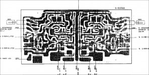
embrown057 (Dr. Emmett Brown?), I was given this amp by a co-worker. She said it was powering some electrostatic speakers of some sort (she didn't specify and I didn't ask). The left channel has never worked for me, and the amp had repair service tags on the cord so I assume it's been worked on before. I used it happily as a mono-amp in the basement hooked up an old (70's era) Jensen speaker. The good channel sounds quite lovely. When I finally got into inspecting it, I found heavy damage on the input board. R601, R633, R635, R637, R639, R661. Q601, and Q611 were all very destroyed (leaving scorch marks on the board). The board itself does not look like the image in the service manual. The front is silk-screened "SMK S394V-0", "016X-1037A01", "Adcom C 1986" and uses horizontal inputs in the back. I can post a picture of just the board, if needed.
Thanks for the assistance!
The best thing you can do in that situation is start new. Carefully check EVERY part with the original schematic. I have no idea if the working channel has been repaired before so unless you are certain double check that channel with the schematic also. I have not repaired as many of these amps as others have but I own a few myself and just finished restoring one of my GFA-555 just last week. Mine also was repaired at one time by someone with less than a working knowledge of this amp. The primary goal here is to restore the board to working order, no crazy upgrades, no designer parts just the way it came from Adcom. Believe me if you do that your amp will be as clean as the day it was built and shipped to the original customer. Never rush anything, cheek and measure twice and then replace & solder. The parts for this amp are still around just do not get transistors off of EBay , most if not all are fake. The board may have burnt foil traces do not panic. The board can always be jumpered with leftover leads from larger resistors, that works for me unless you have massive damage in that case you may have to send the board out to a rework shop for repair or get lucky and find a replacement board that someone does not need anymore. I have the original service manual for that model but will have to ask permission to send it to you or you can call and order it from Adcom if so inclined. The massive amount of resistors that have been replaced sound suspicious and sounds more like someone was on an “Easter Egg Hunt” without a clue.
Attachments
Sigh, I suspect you are correct. Thank you again for your assistance. I will follow your advice. I do have a copy of the Adcom service manual, thanks. Shame they charge $19.95 for them now.The best thing you can do in that situation is start new.
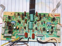
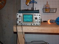
p.s. Attached is the board as removed from the amp, and then my scope trace at 50VAC after repair attempt one. No real reason for posting the pics, everyone loves photos-even of bad repairs.
Attachments
Sigh, I suspect you are correct. Thank you again for your assistance. I will follow your advice. I do have a copy of the Adcom service manual, thanks. Shame they charge $19.95 for them now.The best thing you can do in that situation is start new.
p.s. Attached is the board as removed from the amp, and then my scope trace at 50VAC after repair attempt one. No real reason for posting the pics, everyone loves photos-even of bad repairs.
Attachments


I would also suggest using the Vishay/Dale “RL or RN or even the CMF line of resistors on that board. They will not burn and scorch like the old ones did and are very low noise. Just my option, I use them a lot and they are inexpensive. I have seen a lot worse than your board restored to working condition. I would have liked to seen the view of the foil side just out of curiosity. The other point is watch out for parametric damage to sounding parts, that can really bite you if you’re not careful. The fact that there is damage from the input resistor R601 through the differential pair Q601 & Q603 and onward I would be quite suspicious someone installed some transistors incorrectly (wrong polarity) and or just the wrong parts altogether. The only other time I had seen this was lighting /power surge damage. I would also replace all the electrolytic caps on the board. I see you have more than adequate equipment to facilitate this repair and Shure enough knowledge. Just take your time and patients, as one technician I highly respect told me “follow your inner voice” if you’re not comfortable or have doubts (after testing of course) “Swap it out”. Keep us posted how you’re doing, these are great amps regardless of others hacking them with questionable upgrades.
Thanks for the support, embrown057! I am extremely happy with my equipment (almost all eBay: Scope just over $100, 1KVA Variac just over $50, DMM for under $150) Too bad I can barely use the scope, at least I'm learning though.
I fear that I am bringing my own thread off topic, so for that I apologize. Thanks to the excellent support offered, I am no longer suspecting the 2SA1011 transistor I had originally fingered as the culprit.
I have heard the "replace all the electrolytic caps on the board" advice before, and have done so now (even for the working channel - that was kind of a hard thing to force myself to do...) Don't know if I've mentioned it, but this is my first repair attempt for an amp. There is sooooo much to learn.
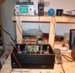
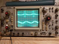
So... On to where I am tonight. I figured before I dissembled everything to test every component, I would do some testing under power with everything connected. I feel the Variac was invaluable here, as I can keep the amp at 50VAC without any smoke or hot components. I went through every component with the O'scope testing each lead with power on and comparing it to the speaker out trace. Most of the circuit exhibited the same oscillation, although one half of the paired input transistors was relatively clean. When I got to Q3 and R14 (Is that the emitter???) I got a very strange trace. I've attached some pictures, sorry for the blur - I was trying to capture the full wave and needed a longish exposure to do so (needed a tripod).
My question: Does this indicate that Q3 is bad? I intend to remove/replace/test regardless, but if someone can say "THAT IS IT!" I would be very happy.
Thanks again!
--Dale (Acceler8)
I fear that I am bringing my own thread off topic, so for that I apologize. Thanks to the excellent support offered, I am no longer suspecting the 2SA1011 transistor I had originally fingered as the culprit.
I have heard the "replace all the electrolytic caps on the board" advice before, and have done so now (even for the working channel - that was kind of a hard thing to force myself to do...) Don't know if I've mentioned it, but this is my first repair attempt for an amp. There is sooooo much to learn.
So... On to where I am tonight. I figured before I dissembled everything to test every component, I would do some testing under power with everything connected. I feel the Variac was invaluable here, as I can keep the amp at 50VAC without any smoke or hot components. I went through every component with the O'scope testing each lead with power on and comparing it to the speaker out trace. Most of the circuit exhibited the same oscillation, although one half of the paired input transistors was relatively clean. When I got to Q3 and R14 (Is that the emitter???) I got a very strange trace. I've attached some pictures, sorry for the blur - I was trying to capture the full wave and needed a longish exposure to do so (needed a tripod).
My question: Does this indicate that Q3 is bad? I intend to remove/replace/test regardless, but if someone can say "THAT IS IT!" I would be very happy.
Thanks again!
--Dale (Acceler8)
Attachments
I would suggest you not even power the unit back up at this time due to the catastrophic damage to that one channel. The amp has fuses on the output boards and if you want to check to make sure the one channel you believe is working, remove the fuses from the dead channel and power it up. This amp will show sign of oscillation if the power is not up to threshold. Just watch your amp meter on the variac for over current draw. I still would not power the amp up till you straighten out that mess on that one channel. There is no way to realistically evaluate the different stages on that circuit without all the parts in place. I know it’s a lot of work to pull all the devices on that board and test them but you have no choice. The one good thing is you have parts that will not require testing like the burnt ones. You need to just replace and the caps also (electrolytic). I would also order a small batch of each transistors so you can match the Hfe as close as possible 10 or so is all I ever order of each. The drivers and predivers 4-6 for each should be fine unless your pockets are deep order more. I order my original transistors from http://www.bdent.com/ make sure you get the correct gain group (Hfe) of the transistor. I would look at the good channel and check which Hfe class was used and just order the same type. The resistors and caps you can get from Mouser Electronics if so inclined. My main point here is first and foremost, repair the input board first. Even if you ordered every part on that channel the cost would me nominal. The real money will be in rebuilding the outputs if needed. The output sections will still have to be evaluated. Even if all the transistors and emitter resistors are fine I would still dismount all the outputs (both channels) and replace the mica insulators and thermal grease. The grease dries out after a period of time, take caution if you considering using silicon insulators, most are unsuited for this application. Laird Technologies has a T-Gard 210 that has a very high puncture/tear resistance but may be hard to obtain. Just take your time, use your DVOM and transistor tester to look at every part in that channel. I would also suggest start a log and copy the data from your finding s, that way you will have a reference to order parts also. I still would like to see a picture of the foil side of that board. Keep us posted.
- Status
- Not open for further replies.
- Home
- Amplifiers
- Solid State
- 2sa1011 Transistor Test