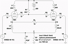
Was wanting to increase open loop gain before applying cathode feedback.
Any lower open loop gain, G1 would need swing so far as might get into A2.
I still wanted full output power, but didn't want to fight with A2.
Falling screen is negative feedback on one half cycle, trying to make up
the lost gain with falling screen as positive feedback the other half cycle.
What ends up gettin' fed back to screen is almost pure 2nd harmonic.
Strangely, this doesn't seem to cause any significant problem???
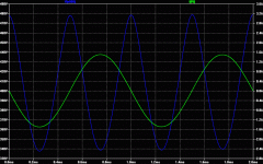
V(n005) is the graph of the screen voltage, compare to load current.
This sim'd less screen current overall than screens at fixed voltage.
But probably depends the model. I want to rerun experiment with 6L6.
This inductor ratio transforms 16 up to about 6600 plate to plate?
Not accounting for any small OTL bonus due to cathodes directly
coupled to the load...
Attachments
Last edited:
Looks like it would always be neg. fdbk for the actively conducting tube. But some positive feedback for the turning off tube. Which would help the turning off tube turn off faster. Looks to be a similar action to what goes on in an LTP when the tail V swings around. What's the FFT of the screen V look like? Nearly pure 2nd H? And is the final output developing any significant 2nd or 3rd H? Maybe a little of this could compensate the 3rd H of an LTP, or just make it worse. (phase?)
Graphing true screen V, and plotting the true harmonic content is a little
less then straightforward, cause the tube is sitting on a cathode feedback.
Since you be need to lern LTspice nwys, add a 10Meg or higher "measurin"
resistor from screen to cathode and graph FFT of that current instead.
Its having no detrimental effect upon output that I can tell. It might even
be helping??? Probably so by making the open loop more sensitive to the
difference between input signal and cathode feedback. More than if only
negative feedbacks were present at the screens, let me clarify that point.
It should not theoretically be any worse to hold the screen voltage at the
minimum figure, yet somehow I'm getting better results to let it waggle at
the 2nd H. Any earth shattering theories why?
This evolved from a cross-coupled UL thought excercise. But the screen
currents in that configuration were absurd, and added the wrong way to
the main phase dot. I just could not win.
Last edited:
The combined screen current will be antiphase for odd order and in phase for even order, which is why it is mainly second harmonic. Putting this current through the screen resistor produces a screen voltage at 2H. This is neither positive or negative feedback, because it is not at the fundamental frequency. The main consequence of this is to produce some 3H, which may add to or partially cancel the 3H already produced by the valves on their own.
I'm unclear what you were trying to achieve.
I'm unclear what you were trying to achieve.
- Status
- Not open for further replies.

