Hello,
I would like to introduce you to my DIY amplifier. It works with the probably best known transistor, the 2N3055.
Some years ago I was looking for a simple circuit for the 2N3055 and bought a module from China. I built it, but the result was not very good. During my search on the internet I came across El Cheapo.
https://pe2bz.philpem.me.uk/Mi...t-El-Cheapo/project12.htm
https://sound-au.com/project12a.htm
I adjusted the circuit a bit and added a simple but well working quiescent current control. The result is this schematic.

I converted the module from China to this schematic and then installed it in an old Dual case, which I rebuilt.
The result sounds really good. The amp has a warm sound, yet has very fine resolution and imaging. It is supposed to go in the direction of the Quad 303. I have not heard a Quad 303 yet. Since the circuit is similar in basic principle, I can certainly imagine it.
I have already presented El Cheapo in several videos. Who would like to occupy himself with it finds here further info.
Finally, a few months ago, as part of a community project of the german www.Dual-Board.de and the www.analog-forum.de, a PCB-board was created on which you can build an El Cheapo. I wrote the assembly instructions, but they are only available in German.


In the meantime there are already three finished replicas. The feedbacks are all positive, the sound seems to convince.


I am currently building a special version, the "El Cheapo compact". I replaced the 2N3055 and the two BD139/140 by two complimentary Darlingstons (MJ901/1001). Thus one can reduce the space requirement strongly. In the driver stage there is no BD140 but a germanium transistor. This makes the sound a bit softer, more tube-like. By the way, the schematic is not completely dissimilar to the "Black Devil" amplifier. However, I use a different quiescent current control.
Finally, the circuit of EL Cheapo and also now EL Cheapo is very variable. You can use many different transistors, adjust the values of the capacitors and electrolytic capacitors, make other modifications. So you can adjust the sound.
I would be happy to start a small discussion here.
Many greetings
Frank
My Youtube-Channel: https://www.youtube.com/@lowpoweramps
I would like to introduce you to my DIY amplifier. It works with the probably best known transistor, the 2N3055.
Some years ago I was looking for a simple circuit for the 2N3055 and bought a module from China. I built it, but the result was not very good. During my search on the internet I came across El Cheapo.
https://pe2bz.philpem.me.uk/Mi...t-El-Cheapo/project12.htm
https://sound-au.com/project12a.htm
I adjusted the circuit a bit and added a simple but well working quiescent current control. The result is this schematic.
I converted the module from China to this schematic and then installed it in an old Dual case, which I rebuilt.
The result sounds really good. The amp has a warm sound, yet has very fine resolution and imaging. It is supposed to go in the direction of the Quad 303. I have not heard a Quad 303 yet. Since the circuit is similar in basic principle, I can certainly imagine it.
I have already presented El Cheapo in several videos. Who would like to occupy himself with it finds here further info.
Finally, a few months ago, as part of a community project of the german www.Dual-Board.de and the www.analog-forum.de, a PCB-board was created on which you can build an El Cheapo. I wrote the assembly instructions, but they are only available in German.
In the meantime there are already three finished replicas. The feedbacks are all positive, the sound seems to convince.
I am currently building a special version, the "El Cheapo compact". I replaced the 2N3055 and the two BD139/140 by two complimentary Darlingstons (MJ901/1001). Thus one can reduce the space requirement strongly. In the driver stage there is no BD140 but a germanium transistor. This makes the sound a bit softer, more tube-like. By the way, the schematic is not completely dissimilar to the "Black Devil" amplifier. However, I use a different quiescent current control.
Finally, the circuit of EL Cheapo and also now EL Cheapo is very variable. You can use many different transistors, adjust the values of the capacitors and electrolytic capacitors, make other modifications. So you can adjust the sound.
I would be happy to start a small discussion here.
Many greetings
Frank
My Youtube-Channel: https://www.youtube.com/@lowpoweramps
Last edited:

Hello,
I have actually installed a bootstrap in test the circuit. This allowed me to achieve about 5-10% higher output with the same operation voltage. However, the circuit works very symmetrically even without bootstrap. The lower gain can be compensated with a slightly higher operating voltage. The slightly lower gain can be compensated by the negative feedback.
The big advantage of not using a bootstrap is that the tendency to self-oscillations is significantly reduced. So you can put 20 cm of wire between the board and the transistors and NTC without any problems and without self-oscillations. This increases the reliability of the rebuild.
Kind Regards
Frank
My Youtube-Channel: https://www.youtube.com/@lowpoweramps
My El Cheapo runs with 35 Volts.
I have tested with 30-50 volts. It works fine with that. However, at over 35 volts, the small heat sinks on the PCB-board are no longer sufficient.
The original circuit runs with 70 volts, I have not tested such high voltages, but I am sure that it also runs perfectly with > 50 volts.
Kind regards
Frank
My Youtube-Channel: https://www.youtube.com/@lowpoweramps
Rod Elliot runs 60 V.
35 V will be just fine.
R9
17/2.2 = 7.7mA in that stage, which still is a bit on the high side
35 V will be just fine.
R9
17/2.2 = 7.7mA in that stage, which still is a bit on the high side
This circuit diagram is close to those of the "Black Devil", an amplifier diy project published in Germans magazine ELRAD - go to attachments in post #39 under
https://www.diyaudio.com/community/threads/your-opinion-about-this-schematics.154493/page-2
and this threads:
https://www.diyaudio.com/community/threads/black-devil-improved.295996/
https://www.diyaudio.com/community/threads/input-bjt-selection-for-black-devil-amp-elrad.329681/
I am now looking for a power amplifier approach that is even simpler and only consist of one VAS stage, which is an input stage at the same time (of course additional a complementary or quasi-complementary output power buffer resp. power follower.
This was my first diy amp (realized in late 70s) with 2N3055 from RCA and was my first good working amplifier.
This power amp operates in the inverted mode with relatively low input impedance.
Unfortunately it was stolen from me during my military training in 1978 or 1979.
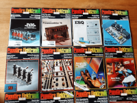
If I remember correctly, the associated article for this diy project was published at the end of the 70s in the German issues "Popular Electronics" ("Populäre Elektronik") - the title was in Germany "Puzzle Verstärker" - check out fourth magazine in the attached image.
Maybe one of the member can upload the article or at least the schematic diagram.
Thank you very much.
The Renardson MJR amps operates also only in an inverted mode and with one voltage gain stage, but instead only one transistor he prefer at this place a darlington transistor in a cascode configuration - go to
https://www.diyaudio.com/community/threads/mjr-7-mosfet-amplifier-of-m-renardson.125650/
https://www.diyaudio.com/community/threads/your-opinion-about-this-schematics.154493/page-2
and this threads:
https://www.diyaudio.com/community/threads/black-devil-improved.295996/
https://www.diyaudio.com/community/threads/input-bjt-selection-for-black-devil-amp-elrad.329681/
I am now looking for a power amplifier approach that is even simpler and only consist of one VAS stage, which is an input stage at the same time (of course additional a complementary or quasi-complementary output power buffer resp. power follower.
This was my first diy amp (realized in late 70s) with 2N3055 from RCA and was my first good working amplifier.
This power amp operates in the inverted mode with relatively low input impedance.
Unfortunately it was stolen from me during my military training in 1978 or 1979.
If I remember correctly, the associated article for this diy project was published at the end of the 70s in the German issues "Popular Electronics" ("Populäre Elektronik") - the title was in Germany "Puzzle Verstärker" - check out fourth magazine in the attached image.
Maybe one of the member can upload the article or at least the schematic diagram.
Thank you very much.
The Renardson MJR amps operates also only in an inverted mode and with one voltage gain stage, but instead only one transistor he prefer at this place a darlington transistor in a cascode configuration - go to
https://www.diyaudio.com/community/threads/mjr-7-mosfet-amplifier-of-m-renardson.125650/
Attachments
Without bootstrap distorsion is much higher, that was one of the main shortcoming of an Elektor amp from 1970,Hello,
I have actually installed a bootstrap in test the circuit. This allowed me to achieve about 5-10% higher output with the same operation voltage. However, the circuit works very symmetrically even without bootstrap. The lower gain can be compensated with a slightly higher operating voltage. The slightly lower gain can be compensated by the negative feedback.
The big advantage of not using a bootstrap is that the tendency to self-oscillations is significantly reduced. So you can put 20 cm of wire between the board and the transistors and NTC without any problems and without self-oscillations. This increases the reliability of the rebuild.
Kind Regards
Frank
My Youtube-Channel: https://www.youtube.com/@lowpoweramps
and this was despite 3 transistors being used in serial for the OS in the side fed by the resistance w/o bootstrap.
If there s oscillations in the OS increase C5 up to 330pF.
I came across El Cheapo
El Cheapo is a nice tube amp, we made a variation, and except for power, was right upwith my SIT-3.
https://www.diyaudio.com/community/threads/el-cheapo-pp-6aq5-6v6-el84.154285/
dave
when remove the emitter follower at the input in the circuit underI am now looking for a power amplifier approach that is even simpler and only consist of one VAS stage, which is an input stage at the same time (of course additional a complementary or quasi-complementary output power buffer resp. power follower.
This was my first diy amp (realized in late 70s) with 2N3055 from RCA and was my first good working amplifier.
This power amp operates in the inverted mode with relatively low input impedance.
Unfortunately it was stolen from me during my military training in 1978 or 1979.
If I remember correctly, the associated article for this diy project was published at the end of the 70s in the German issues "Popular Electronics" ("Populäre Elektronik") - the title was in Germany "Puzzle Verstärker" - check out fourth magazine in the attached image.
Maybe one of the member can upload the article or at least the schematic diagram.
Thank you very much.
The Renardson MJR amps operates also only in an inverted mode and with one voltage gain stage, but instead only one transistor he prefer at this place a darlington transistor in a cascode configuration - go to
https://www.diyaudio.com/community/threads/mjr-7-mosfet-amplifier-of-m-renardson.125650/
https://sound-au.com/project12a.htm
then one have the asked topology.
The original project mentioned from Rod Elliott (el cheapo 2-30, Audio, November 1964) you will find in the attachment.
There are also a power follower topology under
https://makingcircuits.com/blog/simple-100-watt-amplifier-circuit-using-2n3055-transistors/
maybe an old version of those under
https://www.diyaudio.com/community/threads/quality-in-a-cool-follower-99.12542/
but I don't know about the stability of quiescent current resp. idle current through the output devices.
Attachments
- Home
- Amplifiers
- Solid State
- 2N3055 "El Cheapo" Amp