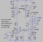
Why redundant D4 & D5?
When you have D1, D2, D3 for low voltage references?
oops. Just noticed D1 D2 are 1N types...
Not enough voltage here to bias 2SK.
When you have D1, D2, D3 for low voltage references?
oops. Just noticed D1 D2 are 1N types...
Not enough voltage here to bias 2SK.
revintage said:The 6B4G grid is at ca 200V potential.
So the cathode is about +250. I'm having trouble visualizing what
happens to the voltage at the MOSFET drain. It must swing opposite
the anode voltage. The reason I ask is that I think you will need
headroom for the drain swing negative equal to anode voltage
positive swing and MOSFET voltage rating to accommodate positive
drain swing equal to the anode negative swing, e.g. about a 500V
MOSFET. Is this correct?
Michael
PS the anode voltage rating on the 6S45pi data sheet is given
as 150V "Limit Value". Any idea what the real max anode voltage
op point is for these?
The top end of the drain winding is ultrapathed to B+,
and varies barely any more than power supply ripple.
The drain end sees its own quiescent voltage, minus an
opposite swing of whatever might happen at the plate.
The plate winding may bootstrap itself to swing not
more than twice the plate's quiescent voltage drop.
and varies barely any more than power supply ripple.
The drain end sees its own quiescent voltage, minus an
opposite swing of whatever might happen at the plate.
The plate winding may bootstrap itself to swing not
more than twice the plate's quiescent voltage drop.
kenpeter said:The top end of the drain winding is ultrapathed to B+,
and varies barely any more than power supply ripple.
The drain end sees its own quiescent voltage, minus an
opposite swing of whatever might happen at the plate.
The plate winding may bootstrap itself to swing not
more than twice the plate's quiescent voltage drop.
Yes, it looks like it should operate at about PS midpoint for best
efficiency and balanceds swing on both windings. Nice indeed for
direct coupling also! Just about the right grid voltage for the driver anode.
Only one thing left to think about... How to drive that MOSFET with
an anti-triode signal current mirror. Is it time for the Hall effect
coupling yet?
Michael
L12 + C7 try to keep the drive signal common mode to GND.
But the Ultrapath and CCS float entire output on B+ noise.
Could PSRR improve to drive in common mode with noise?
Rather than waste extra parts to oppose it with L12 + C7?
Examine Loftin-White input stage, as abused in my example.
Hard to tell my intent from the schematic alone, cause I
didn't bother to fill in all the component values. Four things
are supposed to happen simultaneously at input cathode:
DC Bias (obvious)
1/Mu gain degenerated by cathode resistor
1/Mu gain regenerated by positive feedback
1/Mu sample of B+ noise
The net effect at the plate is full Mu gain as-if no resistor
at the cathode, and drive signal fully common to B+ noise.
Or you can abuse pentode, cascode, or sand to get the
input's PSRR as awful as possible, which is actually good.
Its good when output also happens to float on ultrapath
noise, as both your and my example do.
You don't need any Loftin-White style feedback with the
high impedance devices, only applicable if you choose to
stay with a low impedance single triode. Doing both is
unnecessary.
Hey guys,
This amp is exactly as sensible to B+ ripple as a standard SE with parafeed cap. Must design the PSU now. How low should 100Hz ripple(mV RMS)be at the output?
This amp is exactly as sensible to B+ ripple as a standard SE with parafeed cap. Must design the PSU now. How low should 100Hz ripple(mV RMS)be at the output?
Received the toroids for this and other projects from Antek today. Back to the original idea with the CCS(now hybrid MOS/BJT) on top as it has far better PSRR. Also with resistor-load on 6C45 you get distortion-cancellation that can be fine-tuned with R22.
Attachments

Nein, Herr Besserwisser!
This is an exciting amp configuration. The rest is only a matter of semantics.
This is an exciting amp configuration. The rest is only a matter of semantics.
revintage said:Nein, Herr Besserwisser!
This is an exciting amp configuration. The rest is only a matter of semantics.
Hello revintage,
read some books about electronics fundamentals
and read the forum rules 😉
thanks.

Again Herr Besserwisser,
I have kindly asked you before not to participiate in my threads. Please respect this! As you have nothing to add about the original subject, why do you interfere? If you don´t like my attitude please contact an administrator about this.
I have kindly asked you before not to participiate in my threads. Please respect this! As you have nothing to add about the original subject, why do you interfere? If you don´t like my attitude please contact an administrator about this.
revintage said:Again Herr Besserwisser,
I have kindly asked you before not to participiate in my threads. Please respect this!
Lars, is this your forum?
I participate where I want.
You are able to call me names in German language.
Take some time and read the text attached here.
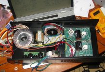
antek transformers
revintage,
just found this thread, and have wanted to try a small tube amp, this looks like a good try and a great learning experience.
now, i apologize for my newbie status, particularly on the issue of transformers, but can i ask -- the antek transformers are 'power transformers'? with dual 115v primaries and a 6.3v secondary? this is what you are using? the primaries link the tube to the load, and the secondary goes to the b+? do you have a part number for the transformer?
do i have that correct? (again, apologize for the level of the question.)
i'll do the required reading on the parafeed circuit, but i thought i might have some transformers like you used, and that could get things off the ground without having to buy a whole bunch of stuff.
thanks,
ron
Hi Ron,
You have to unwind a 115+115V:6//6V mainstoroid until you have a open circuit secondary voltage that corresponds to between 2,5k:8 and 3k:8.
You have to unwind a 115+115V:6//6V mainstoroid until you have a open circuit secondary voltage that corresponds to between 2,5k:8 and 3k:8.
Unwind? I calculate 2K939 right off the bat? What gives?
8*(((115+115)/(6+6))^2)=2938.8888888888_
And 2K666 if the secondaries might actually be 6.3V
8*(((115+115)/(6+6))^2)=2938.8888888888_
And 2K666 if the secondaries might actually be 6.3V
kenpeter,
You can not take copper-losses at full load in account when you calculate.
Unloaded secondary!
For a typical 6V, 30VA this corresponds to 6,8V which means ca 2,3k:8. I have not measured the Antek yet, will come back.
You can not take copper-losses at full load in account when you calculate.
Unloaded secondary!
For a typical 6V, 30VA this corresponds to 6,8V which means ca 2,3k:8. I have not measured the Antek yet, will come back.
Just checked the Antek AN-0206, 25VA, 6V and it was extremely low compared to Talema that are 6,8V. It was 6,1V unloaded and with 2.8k:8ohm for 115:6,1V there is no need for unwinding😎.
Remade a pair of Talema 50VA 12V for the SEPTOR and had to unwind 2*14 turns to make it a 3k:8ohm PP.
Remade a pair of Talema 50VA 12V for the SEPTOR and had to unwind 2*14 turns to make it a 3k:8ohm PP.
Hi Ron,
Reread your post:
The two primaries are series-connected in anti-phase to B+(with only the lower as tube load) and the two secondaries are parallelled at the output.
But do not try it yet as this is still a prototype based on the schematic in post#47.
Reread your post:
the primaries link the tube to the load, and the secondary goes to the b+?
The two primaries are series-connected in anti-phase to B+(with only the lower as tube load) and the two secondaries are parallelled at the output.
But do not try it yet as this is still a prototype based on the schematic in post#47.
revintage said:Remade a pair of Talema 50VA 12V for the SEPTOR and
had to unwind 2*14 turns to make it a 3k:8ohm PP.
That seems an awfully small number of secondary
turns to justify tearing apart the factory wrapping.
Suppose one added an extra 28 turns wired up
the "wrong way", does it have the same effect?
- Status
- Not open for further replies.
- Home
- Amplifiers
- Tubes / Valves
- 2A3 SE parafeed with PP-transformer