It's kind of like the anti-triode version of this push-pull topology
Oops, crossed posts with Ken; Yup, that's it. The MOSFET is
suitably enslaved by the triode
Another advantage of Lars' circuit is the nice series regulation of the
DC current, inherently balanced through the transformer. I wonder
if the transformer winding technique would be different with the
signal polarity being reversed between the two halves of the primary?
Michael
Attachments
I think the B+ is well used if you are getting output power out of it.
One thing to note is the components, MOSFET, bypass cap, etc.
should be rated for the full B+. Also the B+ on the tube could
exceed ratings under some transient or startup conditions.
I'm building a series regulated amp using 300Bs and have 700V
on the B+. I did have to go to some higher voltage components
like damper diodes, 660V motor runs, etc. which is a little more
cost, still not in 845 territory but approaches 845 power levels.
Cheers,
Michael
The drawback was : Zout!
With regular SE as in my initial post Zout is ca 1ohm. With the "Push-Push" circuit, Zout will be in the ballpark of 6ohm.
Ie this is a current amp!
With regular SE as in my initial post Zout is ca 1ohm. With the "Push-Push" circuit, Zout will be in the ballpark of 6ohm.
Ie this is a current amp!
+/- 350 with center tap grounded??? Any less hazardous???
Startup conditions, transients, whatever...
I mean, you'd have similar center tap cap(s) (top and bottom),
but those then share the same topology as the power supply.
I think the total part count comes up the same either way.
I refer to the interstage transformer example only.
-----------------------------------------------------------------
If the voltage supply(s) were to replaced by current source(s)
Or chokes (as in CLC, where the final C's are center tap caps)
Those same caps just mentioned become the "Brute" bridge.
Same exact thing, only completely different.
Nevermind... "Brute" has no center point forced to GND.
Not the same thing, I just go confuse myself is all...
Brute could be done with a 1:1 interstage instead of a cap.
That would get rid of the series resonance...
Possible that bridge windings could even share the same
magnetic circuit with the OPT? I'm not too sure bout that.
I can't quite wrap my mind around what would happen.
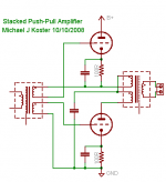
Don't have a symbol for 3 way switches for the screens,
use your imagination. The "brute" cap was deliberately
illustrated as disconnected, no imaginary switch implied.
That would get rid of the series resonance...
Possible that bridge windings could even share the same
magnetic circuit with the OPT? I'm not too sure bout that.
I can't quite wrap my mind around what would happen.
Don't have a symbol for 3 way switches for the screens,
use your imagination. The "brute" cap was deliberately
illustrated as disconnected, no imaginary switch implied.
Attachments

revintage said:The drawback was : Zout!
With regular SE as in my initial post Zout is ca 1ohm. With the "Push-Push" circuit, Zout will be in the ballpark of 6ohm.
Ie this is a current amp!
Hi Lars,
In all of my experiments, the MOSFET current-slaved to the triode
acts like a second triode, and yours is too, I think.
The reason for your high output impedance is the unbypassed cathode
resistor, which multiplies through the mu of the tube. The MOSFET is
only mirroring this high anode impedance through it's sensing of
cathode current.
Try this: Bypass all but 100 ohms of the cathode resistor with a cap
and reduce the R29 divider ratio accordingly (by 1/15). You should
see the output impedance drop to give you a voltage amp again ;-)
Cheers,
Michael
Hi Michael,
Your idea of partly bypassed was no success when simmed. Instead I did a CF from the drivers output. Better, but it doesn´t work either as you for some reason loose top-end. In the case when feeding from the unbypassed carthode some resonance made it work up to 70k. Knowing that the MOSFET models aren´t reliable, the results may be different IRL.
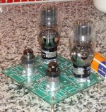
So I give up on the "Push-Push" for now and build the amp as SE first. On the pic is the PCB with NOS E280F as driver.
Your idea of partly bypassed was no success when simmed. Instead I did a CF from the drivers output. Better, but it doesn´t work either as you for some reason loose top-end. In the case when feeding from the unbypassed carthode some resonance made it work up to 70k. Knowing that the MOSFET models aren´t reliable, the results may be different IRL.
So I give up on the "Push-Push" for now and build the amp as SE first. On the pic is the PCB with NOS E280F as driver.
Attachments
Hi Lars,
Interesting results, but there are a lot of variables after all. It works
in parallel but maybe not in series for some reason...
Nice looking PCB!
Michael
Interesting results, but there are a lot of variables after all. It works
in parallel but maybe not in series for some reason...
Nice looking PCB!
Michael
Beginning to look like another one of my half baked ideas
I never seem to get around to building... Same thing, yet
completely different.
Mine had no ultrapath cap for the cathode, and thus the
output triode was locked by cathode winding feedback to
a voltage gain of 2. Input stage was pseudo Loftin-White,
and the whole output floated with B+
Smoking and Oldie called it a "Single Ended Circlotron"
which is about the least accurate description I could
ever have come up with... But those would be words
to search if you wanted to compare drawings.
Hi kenpeter,
That was a completely differant animal! With balanced currents it is more towards an AT but without AT😉! Are the multilegged kritters IGBTs?
About mine I feel a lot more comfortable with the sand closer to ground😀!
Have never tested the C4S styled CCS with BJT/MOS mix, any objections? Off course there should be gatestoppers etc.
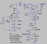
revintage said:Did some more thinking and moved the tertiary and the CCS to the cathode side. We can now use NMOS 2SK2700 from Hoktunas stash! 6B4Gs grid potential is dependant on the current through the 6C45 and also the cost of an expensive coupling-cap is saved😉 !
Looks to me like a SE with a bipolar/MOSFET cascode CCS in the
cathode; AC output signal current returned through the 220uF cap
directly. I used this circuit for the D3a driver in my latest 300b amp.
It works well if you choose a linear op point.
Michael
Hi Michael,
Did you really use a mains-toroid with half of the primary in the cathode circuit for current eq? I will probably use a triode-strapped E280F(not far from D3a) as driver.
Did you really use a mains-toroid with half of the primary in the cathode circuit for current eq? I will probably use a triode-strapped E280F(not far from D3a) as driver.
revintage said:Hi Michael,
Did you really use a mains-toroid with half of the primary in the cathode circuit for current eq? I will probably use a triode-strapped E280F(not far from D3a) as driver.
I see it now. You are putting the other primary winding in the
cathode branch. How much signal voltage swing do you see
across the cathode side winding?
I first thought you were using D3As by the look of the tube. They
do seem similar, the D3A having a little higher gm and higher mu.
Cheers,
Michael
revintage said:About mine I feel a lot more comfortable with the sand closer to ground😀!
The gates are grounded, whats the trouble?
- Status
- Not open for further replies.
- Home
- Amplifiers
- Tubes / Valves
- 2A3 SE parafeed with PP-transformer