This subject has been up in another thread where it drowned in the very interesting PP anti-triode discussion. This one is purely SE in contrary to what I first thought. As L4 a Hammond 150H/8mA can be used.
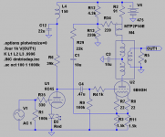
To be able to use a PP-transformer the CT has to be split as the windings are connected with their plus-poles against each other.
This way the currents are equal and opposed to each other so no(toroid) or a very small gap(PP) is needed. R12 should be adjustable as it sets Iq.
For some reason linearity is better with the input connected to Q2s collector. Maybe the CCS works as an anti-triode?
An externally hosted image should be here but it was not working when we last tested it.
About the transformers the PP should be between 10-12kohm. The toroid should have an unloaded secondary of between 5,9-6,5V.
Got second thoughts on version 2. If the parafeed cap is connected to ground instead the amp might work as an anti-triode. What do you say kenpeter😉 ?
Did some quick sims and clipping occurs at the same time but distortion is halved at 1W/8ohm! At 3% the #1 gives 2,1W and #2, 2,9W. It did not work very well with the 6B4G cathode decoupled to ground and the parafeed cap to ground.
But as the results are simmed they are not completely reliable, but they point in some anti-triode direction😎.
And it is notNFB as the signal out is higher from#2.
Was a little to enthusiastic about #2. The sand input is in the region of 500ohm so it will not be a practical solution.
Was a little to enthusiastic about #2. The sand input is in the region of 500ohm so it will not be a practical solution.
2 silly questions:
If you want to modulate your current source why do you not apply an "Aleph" current source a la Nelson Pass? Btw. , there are transistors with higher beta that you can use instead of BD140.
Secondly, from a theoretical standpoint, if your intention is to cancel the DC bias current in the output transformer, would you not try to bypass the upper half of the primaries with a cap, to remove AC current?
But maybe I am misinterpreting your intentions.
Hello Martin,
My only intention is to use a PP(or toroid) as SE OPT as subject shows.
1 Have no clue about it. Please show a schematic. But I think I will skip #1 anyway.
2 There is only problem, it will not work with a bypass cap 😉. But it was a good idea!
As this is an el Cheapo/Simplo SE, the CCS will be made even simpler with only the MOSFET, 3 LEDS and 3 resistors. Like this:
An externally hosted image should be here but it was not working when we last tested it.
Hello Lars,
Re. Aleph current source: All explained in http://www.passdiy.com/articles.htm - Zen Variations 2: The Penultimate Zen's Current Source by Nelson Pass - well worth reading, but then again I am not sure if modulating the current source is a good idea in conjunction with the transformer.
I do not readily understand why it would not work other than you would off course create a parallel resonant circuit? And yes it would be nice to keep the current constant.
Re. Aleph current source: All explained in http://www.passdiy.com/articles.htm - Zen Variations 2: The Penultimate Zen's Current Source by Nelson Pass - well worth reading, but then again I am not sure if modulating the current source is a good idea in conjunction with the transformer.
2 There is only problem, it will not work with a bypass cap . But it was a good idea!
I do not readily understand why it would not work other than you would off course create a parallel resonant circuit? And yes it would be nice to keep the current constant.
Hello again Martin!
I use LTSpice to test all my more or less smart ideas. It is a handy tool that saves a lot of time. Also there is no smoke when you fail😀 !
I tried your suggestion before saying it will not work. The reason it will not is that you short a winding when bypassing it with a cap.
I use LTSpice to test all my more or less smart ideas. It is a handy tool that saves a lot of time. Also there is no smoke when you fail😀 !
I tried your suggestion before saying it will not work. The reason it will not is that you short a winding when bypassing it with a cap.
revintage said:Got second thoughts on version 2. If the parafeed cap is connected to ground instead the amp might work as an anti-triode. What do you say kenpeter😉 ?
SE Sand opposing SE Triode in DC balance is not anti-triode.
Where does it sample the Triode to mime an anti-behavior?
Applying arbitrary modulation by some other computation,
even a very linear-izing one, not quite the same...
Yours is a fine circuit, maybe even a great one. I'm only
nitpicking over a topology definition, I don't think it fits.
Came to the same conclusion with a little help on the way by Martin. The modulated current source makes things easier for the triode and thereby lowers distortion. Unfortunately there seems to be both stability and HF-problems so I skip it for now.
Yes, ZEN's "Aleph" current sink appears to be an anti-FETron.
If somewhat overcomplicated for one thats supposed to be
the heart of simplicity... I still prefer MJK's variant.
If Nelson had only used a Triode in the lower half, instead of
a FETron emulating a Triode, well you can guess the rest...
Another victim of the "Glass Curtain".
I very much doubt he realizes the entire truth of what he's
actually done by externally reconnecting "Mu" in a MOSFET.
Last I exchanged words with Pass, he still believed a Triode
emulator was a cascode of two voltage starved JFETs.
Brilliant, but at the same time, go figure...
Mu Follower style current sink, with load tapped halfway up the
sense resistor. Much lower parts count for the same result...
You know any other MJK's?
sense resistor. Much lower parts count for the same result...
You know any other MJK's?
kenpeter said:You know any other MJK's?
Martin J King... develper of transmission line simulation software.
dave
Where to start? I think I'll unwind...
I changed my moniker from MJK to my real name because Martin
King already had been using MJK, and also for transparency.
Many have come close and skirted the truth of the anti-triode.
I think it's just a little too evil at first blush. But you come to love
it over time ;-) I'll definitely want to hook up with Nelson at Burning
Amp if there's time.
Inverse signal current mirror is a more descriptive name, but anti-
triode describes how it dynamically functions in the circuit, acting
as if you had a device with the exact opposite bend in the transfer
function curve. As Ken says, you get this by driving the mirror
element be it BJT, MOSFET, pentode, or cascode, in current mode,
from the inverse of the signal current of the active element
(controlling triode). There are about a dozen ways and counting.
I'm not sure which of the 3 or 4 variants I have tried Ken is referring
to; I'm currently working a series totem-pole I like a lot, and a
parallel ultra-simple scheme. Oh and I fixed the H-bridge thing
with a servo-gyrator...
Your simple current source using LEDs and P-FET could be replaced
with a 10M90 and 2 resistors in the standard depletion mode circuit
with the source on the end of the winding.
I'm interested in an anti-triode version of this one. My two most
recent amps are totem-pole-parafeed and I think this is similar,
but with the DC-balanced transformer inserted where the shared
circuit node of the totem pole would be. It's definitely elegant and
a shame to waste all that voltage on a passive CCS...
Thanks,
Michael
PS This is a very interesting topology; there are a lot of interesting
variations with that OPT primary connection.
OOOOPS😀 😎!
This one sims beautifully! Below .5% distortion up to symmetrical clipping at above 3W/8ohm. -3dB 8Hz-70kHz. Probably to good to be true😕. Probably some evil NFB involved but sensitivity is exactly as the one in my first post.
Cant explain the circuit more than it is SE with an AC-modulated, very simple CCS.
Anyway I have the tubes, sand, PCB, chassi and is only waiting for a new shipment of toriods. Can not decide wether to use 6C45 or triode-strapped E280F, have both!
Attachments
Triode vs Sand in Paraphase??? Not sure if its an Anti...
It does reference the triode, but doesn't seem to follow
through by forcing the sand to do anything un-sandishy.
It does reference the triode, but doesn't seem to follow
through by forcing the sand to do anything un-sandishy.
No kenpeter, it´s no anti-triode and it wasn´t ment to be. Don´t know what to call this little creature😉 .
But you are so right, one gets a paraphase feeling......
But you are so right, one gets a paraphase feeling......
And if the slave end should behave in any manner but "Anti"
The master device will hear the inverse of all misbehaviors
imposed upon its plate (at opposite end of the transformer).
Triodes are sensitive to plate voltage, and will not behave
as expected if you modulate the plate in an undefined way.
Emulating something alien, not a triode. How then can our
distorted reference triode ever be an accurate reference?
The only modulations that do not alter the behavior of the
master device (if that device is load sensitive), are identical
devices (real or emulated) operating in parallel on the same
end of the transformer. Or true "Anti" versions operating
from the opposite end.
Even these modulations "alter" behavior or the master,
but only as-if true load impedance were equally shared.
I think it reasonable hypothesis that identical paralleled
triodes would then be similar to one much larger triode.
Arbitrary, complementary, blended, and/or error correcting
modulations are something else entirely. Can change the
reference behavior of the master device. Perhaps related,
but quite different from Device/Anti-Device SEPP theory...
revintage said:OOOOPS😀 😎!
This one sims beautifully! Below .5% distortion up to symmetrical clipping at above 3W/8ohm. -3dB 8Hz-70kHz. Probably to good to be true😕. Probably some evil NFB involved but sensitivity is exactly as the one in my first post.
Cant explain the circuit more than it is SE with an AC-modulated, very simple CCS.
Anyway I have the tubes, sand, PCB, chassi and is only waiting for a new shipment of toriods. Can not decide wether to use 6C45 or triode-strapped E280F, have both!
It is an anti-triode after all. The sensing resistor is the 750R 6B4
cathode resistor. An AC voltage corresponding to the 6B4 cathode
signal current is communicated via C1 to the voltage divider node
R29 and R12||R13, which causes a signal current to be imposed
through the MOSFET based on the signal voltage and the 91R mirror
resistor. The MOSFET signal current will be inverse the 6B4. The
cap to ground at the CT of the OPT allows the signals to add.
Working out the ratios, the MOSFET provides about a 1.3:1 current
ratio or "boost", modulo it's gfs. This causes the 6B4 to "see"
a larger share of the total primary impedance (smaller share of the
load).
This is just like the first one of these I built, only with the MOSFET
branch polarity reversed and "stacked". This is a very clever idea,
basically it is the anti-triode version of the earlier circuit.
One drawback might be PSRR, but there are plenty of ways to deal
with that.
Cheers,
Michael
PS Spice allows you to probe the waveforms at various circuit
nodes. Lars, you might be able to confirm some things about the
circuit operation by observing the voltage across both the 6B4
bias resistor and the 91R on the MOSFET source. From that you
can calculate the signal current ratio.
Also, your 6B4 operates with unbypassed cathode bias, which will
increase the anode resistance. What driving voltage does it take to
get 3 watts (also, what's the primary impedance?) that's a form
of NFB that could explain the low distortion. This circuit ought to
be able to generate 6-8 watts.
PPS one thing to try would be to bypass most of the cathode R but
leave enough for sensing the cathode current, like 100R or so, at the
ground side, unbypassed. Then reduce the voltage divider ratio R29,
etc., maybe use a little bigger cap, so the overall ratio is 1:1 to 1.5:1
signal current between the MOSFET and 6B4.
Didn't see at first though the odd topology, but its 1.35/1 Anti...
If the Gm of your MOSFET is high as I think it is, slave behavior
should overwhelm all sand behavior. The reference triode will
not be "poisoned at the plate" by any help that seems other
than parallel triodey.
If the Gm of your MOSFET is high as I think it is, slave behavior
should overwhelm all sand behavior. The reference triode will
not be "poisoned at the plate" by any help that seems other
than parallel triodey.
- Status
- Not open for further replies.
- Home
- Amplifiers
- Tubes / Valves
- 2A3 SE parafeed with PP-transformer