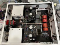
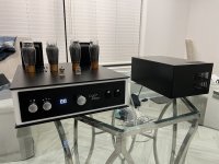
Over the last few months, I've been working on a project inspired by Eddie Current amps. Since those are becoming more and more difficult to find (and I like DIY), I decided to make my own. Uses Monolith Magnetics nanocrystalline interstage transformers, Electraprint silver output transformers with custom tertiary winding, Wein bridge oscillator circuit for a high-frequency filament supply (~44khz VAC for the 2a3 tubes). Case was custom designed by me in Fusion and then Protocase brought it to life. PSU box has the B+ supply using EY500a rectifiers, Toroidy power transformers, Neurochrome soft start. Overall a really fun project and it sounds incredible.

Attachments

You are teasing...
Googled Eddie Current amplifier, and see only sales pitch. Yours seems like totally different design. Please post schematics.
I am curious as to why do you need parallel 2A3s to drive headphones.
Googled Eddie Current amplifier, and see only sales pitch. Yours seems like totally different design. Please post schematics.
I am curious as to why do you need parallel 2A3s to drive headphones.
You are teasing...
Googled Eddie Current amplifier, and see only sales pitch. Yours seems like totally different design. Please post schematics.
I am curious as to why do you need parallel 2A3s to drive headphones.
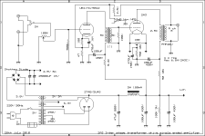
Internally it’s very similar to the Studio T, which is in turn very similar to the standard 417a/2a3 amp design attached. The difference is of course a different rectifier tube, and the interstage transformer is 1:1 at 246 ohm for both primary and secondary. Also, the real trick is the Wein bridge oscillator to generate the high frequency AC for the filaments.
I’m hesitant to post my exact schematic only because it’s so close to the EC amp, and wouldn’t want to ruffle any feathers and draw unnecessary attention lol
Attachments
Moderator, with that kind of answer to my schematic question, Please delete me from this thread.
Thanks!
Thanks!
The schematic looks very 'Oh Hum' to me. Is the Wien Bridge heater circuit Toobz or SS?
Why do the EY500A rectifiers make a difference in the sound? They are isolated from the
audio path by a very effective LP filter as they should be. And yet just another iteration
of a common Damper Diode.
Does the result justify silver wire used in the OPT? Looks like a waste of a natural resource
when copper would more than adequately fill the requirement.
Sine wave on a scope doesn't tell us much. What does a 100 Hz & 10 KHz square wave look like?
Got some THD & IMD plots?
But it does look nice! 🙂
The Wein bridge uses an opamp to generate the sine wave, and an LM3886 for the actual output. Then the toroids step the voltage down and provide oscillation.
And I was just pointing out that it uses a different B+ supply than what’s shown in that schematic.
The partial silver Electraprint wasn’t that much more money, so I figured why not given how invested I was already.
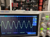
And the scope picture is showing the filament supply sine waves being nearly identical (meaning my winding of those toroids was accurate) and showing the exact frequency they operate at. There’s some variance in the light bulbs used on the circuit, so I had to bin those to get ones that matched.
And I was just pointing out that it uses a different B+ supply than what’s shown in that schematic.
The partial silver Electraprint wasn’t that much more money, so I figured why not given how invested I was already.
And the scope picture is showing the filament supply sine waves being nearly identical (meaning my winding of those toroids was accurate) and showing the exact frequency they operate at. There’s some variance in the light bulbs used on the circuit, so I had to bin those to get ones that matched.
THX for the heads up on those points. But still like to see what happens
to low & high freq square waves as they pass thru the amp. And if you can
some numbers on THD & IMD.
Looking at the detail of the 5842/417A specifications makes me think the DC load for the
driver plate is formed by the 8.2K supply dropping resistor. Off the top it appears that the
plate current is 25-30 mA. Do you have any DC voltage measurements that could be added
to the schematic?
I wondered if 100R CC resistors are used to avoid parasitic oscillation. The high mu &
transconductance look good on paper but in this kind of application can have a serious problems.
This 5842 is good while used as a grounded grid circuit with very short leads at 100 MHz.
But at audio in a typical circuit of larger physical dimensions it looks like many problems. 🙂
Attachments
I‘m very interested in your amp and I hope to build one like yours, hope you can post your exact schematicInternally it’s very similar to the Studio T, which is in turn very similar to the standard 417a/2a3 amp design attached. The difference is of course a different rectifier tube, and the interstage transformer is 1:1 at 246 ohm for both primary and secondary. Also, the real trick is the Wein bridge oscillator to generate the high frequency AC for the filaments.
I’m hesitant to post my exact schematic only because it’s so close to the EC amp, and wouldn’t want to ruffle any feathers and draw unnecessary attention lol
🙂 Thanks
Very nice build. The idea of the wein bridge oscillator is to make the AC such a high frequency that it won't influence phase shift in the audible spectrum?
You could have also just used a DC regulator and a single 2a3 per channel to solve that one... Still beautiful work. 😎
You could have also just used a DC regulator and a single 2a3 per channel to solve that one... Still beautiful work. 😎
Last edited:
I used to use EY500A because they were dirt cheap and nobody wanted to bother with a top cap. Magnoval 9-pin base and a top-cap? Continuous current rating of 440mA? Crazy! and ugly as sin! Best is to mount them on TOP in full view. 😎Why do the EY500A rectifiers make a difference in the sound?
Then I got some dirt-cheap Sylvania 6AU4-GT's which had the ugly coin base and curly-swirly heaters inside. Even better than EY500A since they warm up slower! But yeah, the 6AU4 only has around 200mA continuous current rating. Oh well, my amps are not so powerful anyway 🙂
All dampers "sound" pretty much the same. In my amps they easily sound as nice as high quality SS rectification. But they start up nice and slow.
Yes, you can make SS warm up slow too, but it is more work.
Last edited:
- Home
- Amplifiers
- Tubes / Valves
- 2A3 PSE amp with interstage transformers - Venue