Several years ago I noticed quite a few 26, 27 & 30 enthusiasts trying to use them for their supposed tonal qualities. But the best power triodes all seemed to have MU’s of ~5. There is a fundamental problem; the overall gain is too low. The way out was a third gain stage.
I wondered if anyone had tried a Cascode front end to get the required gain, a search didn’t find much. As a first pass last year I tried simulating a Cascode with a 30 on the bottom & a common medium Mu triode on top. The Cascode triodes do not have to be the same. Just need to be able to handle the plate current.
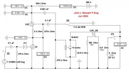
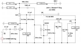
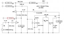
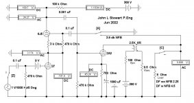
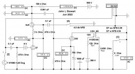
More recently I tried using a 6J5 on top of a 27 in FlaCharlies 6N6G amp. The results looked OK so in the last few days that has been modified to drive a 6L6GC in triode or pentode mode. And a bit further, it turns out the top 6J5 triode grid can be used as a NFB point. The switches in the simulations allow the calculation of NFB, InternalResistance, DF & Sensitivity.
The resulting amp has ~11 db NFB & DF of 3.2. And with a Volt RMS at the input 6W of audio results. Refer to simulation A. I was concerned the NFB might have a loading effect on the 27 but it turns out the load is actually relieved, refer to simulations B & C. With NFB connected the signal at the plate of the 27 doubles. And its gain is ~7.5.
I wondered if anyone had tried a Cascode front end to get the required gain, a search didn’t find much. As a first pass last year I tried simulating a Cascode with a 30 on the bottom & a common medium Mu triode on top. The Cascode triodes do not have to be the same. Just need to be able to handle the plate current.
More recently I tried using a 6J5 on top of a 27 in FlaCharlies 6N6G amp. The results looked OK so in the last few days that has been modified to drive a 6L6GC in triode or pentode mode. And a bit further, it turns out the top 6J5 triode grid can be used as a NFB point. The switches in the simulations allow the calculation of NFB, Internal
The resulting amp has ~11 db NFB & DF of 3.2. And with a Volt RMS at the input 6W of audio results. Refer to simulation A. I was concerned the NFB might have a loading effect on the 27 but it turns out the load is actually relieved, refer to simulations B & C. With NFB connected the signal at the plate of the 27 doubles. And its gain is ~7.5.
Attachments
No, they have Mu much below 5, which for resistance-coupled amplifiers, throws WAY too much work back to the driver.the best power triodes all seemed to have MU’s of ~5.
IOW, for THD like 5% (commercially acceptable for much of history), a common triode can just-about drive that output bottle. If Mu were higher, the output stage with high Rp would bottleneck power. If Mu were lower, an R-C driver stage would be the bottleneck.
Triode power tube loaded conventionally with Rl=2*Rp, 300V supply, will make 200V plate swing. And if Mu is 5, stage gain may be (2/3)*5 or 3.3. 200V plate swing and gain of 3.3 is grid swing of 60V. A lower-Mu driver triode can swing about 20% of B+ as peak audio swing. So to make 60V peak swing we need 300V of driver B+. Which is same as we assumed for power stage B+.
Transformers radically change this "optimum" but have their own problems. With driver transformer we could use Mu of 2.8 or 2.0 or so, gain even lower Rp and/or a little more power output for Pdiss and/or better damping.
All too true. But what I had in mind were the toobz which were commonly used in those circuits,
such as 45, 2A3 & 300B. As we are aware there are many toobz originally meant for deflection circuits
in TV that ,also fit the category well. Using a 27 as a driver with a gain of 7.5 still requires a very large
signal on the front end. And is often fixed with another gain stage.
Not sure were you are going with your statement, have you got a particular circuit in mind?
You have a tube emulation circuit there. The output tube is constrained to match the 27 drive tube curves by the N Fdbk to the cascode grid above.
A DHP like 1E7G (in triode mode) on the bottom should give you remarkable triode curves. 1E7G in triode mode Pic below:
Another way would be to use a high quality (internal triode) pentode like 12HL7 (curve tracer selected) or the 1E7G in pentode with the N Fdbk to the screen grid (instead of the cascode arrangement). 12HL7 triode mode curves, 2nd pic below:
4P1L is another high quality and cheap DHP pentode with great triode curves, 3rd pic:
4th pic is 4P1L in pentode with +15V on grid 3 to square up the knees:
Last edited:
Those curves look great. But the reason for this circuit is to allow the use of a 27, 26 or 30 with all their warts on the front end.
DH tubes on top create another problem. As always, working around these kinds of things requires some tradeoffs.
Here is the cascode driving a 2A3. One Volt RMS on the input grid drives the 2A3 to full output.
Not perfect but yet another solution of many. 🙂
DH tubes on top create another problem. As always, working around these kinds of things requires some tradeoffs.
Here is the cascode driving a 2A3. One Volt RMS on the input grid drives the 2A3 to full output.
Not perfect but yet another solution of many. 🙂
Attachments
The DHT tube would always be on the bottom, so the Htr. power problem is minimized. No top tube even needed with the pentode/screen Fdbk version.
I need some explanation. At 1 mA bias current (somewhat low as operating point for either 27 or 6J5), cascode's output impedance is very high. Wouldn't it cause high frequency roll off due to 2A3 Miller capacitance?
The impedance at the 6J5 plate is the Rl of 100K.I need some explanation. At 1 mA bias current (somewhat low as operating point for either 27 or 6J5), cascode's output impedance is very high. Wouldn't it cause high frequency roll off due to 2A3 Miller capacitance?
More current would help. These simulations are exploratory, looking at what might be possible. 🙂
The cascode is a way of avoiding driving the screen impedance of a common sharp cutoff pentode,The DHT tube would always be on the bottom, so the Htr. power problem is minimized. No top tube even needed with the pentode/screen Fdbk version.
In earlier work I found that to be about 30K, something most people don't plan on.
That PP Class AB2 amp I built about 20 yrs ago used differential cascode for the same reason.
NFB to the upper grids of the cascode.
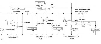
Not long ago I put a 6SJ7/6N6G simulation on DIY for FlaCharlie, But for their own reasons many want
to avoid pentodes as voltage amplifiers. Working around all these preferences tends to get complicated! 😀
My daily driver in the shop is a SE FB pair, pentode/pentode. A 6AU6 driving a 6AQ5. Its been running
without problems since 1968.
Do you really need a 2A3 output tube type? No matter what one puts in there, it is constrained by the N Fdbk to perform just like a type 27 tube. Might as well put the easy to drive 6L6 output tube in there. That's the beauty of the emulation scheme, put a great (and cheap) low power triode in for the type 27 and you get a power version of it for output.
Don't 'really need' any particular toob in that position. Go back to post #1, a 6L6 is used there as you suggest.Do you really need a 2A3 output tube type? No matter what one puts in there, it is constrained by the N Fdbk to perform just like a type 27 tube. Might as well put the easy to drive 6L6 output tube in there. That's the beauty of the emulation scheme, put a great (and cheap) low power triode in for the type 27 and you get a power version of it for output.
Keep front in mind the thread objective to explore the possibility of a cascode front end using one of those ancient triodes on the bottom.
Any number of other topologies are possible. This one is already defined.
The 6SJ7/6N6G I suggested to FlaCharlie in May to solve the Gain problem is attached.
Attachments
As you have pointed out One Ma won't be enough to properly drive a 2A3. In today's sims the capacitive parasiticsI need some explanation. At 1 mA bias current (somewhat low as operating point for either 27 or 6J5), cascode's output impedance is very high. Wouldn't it cause high frequency roll off due to 2A3 Miller capacitance?
of the tubes are included. The sims with the 2A3 were dropping off in the middle of the audio band. The cascode current
was increased but it was almost impossible to put something together that satisfied all the requirements.
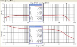
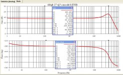
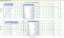
The sim where a 6L6GC is in the output performed much better, Without NFB the response is relatively flat out beyond 30 KHz.
With the NFB switched in there is a peak of ~5 db at 30 KHz, That could be fixed with an RC network across the cascode plate R.
The 6L6GC vers needs NFB, otherwise the DF is too low.
Simulations make design easy compared to what we did with pencil, paper & sliderule.
And there is no smoke or red plating. 😀 👍
Attachments

Do you really need a 2A3 output tube type?
My grasp of the technical aspects of all this is minimal, at best, so I won't comment on those details.The 6SJ7/6N6G I suggested to FlaCharlie in May to solve the Gain problem is attached.
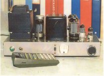
But the amp I built, which I've dubbed the Nuance, uses a one 26 and one 6N6G per channel and it sounds wonderful. It employs the "inverted SET" (iSET) topology that Andy Evans was promoting for a while. The basis of that is simply to use a single directly heated input tube and an indirectly heated output that's easy to drive.
When I had the amp breadboarded I tried a wide variety of low mu, directly heated, input tubes. Some triodes, some triode strapped pentodes. The 26 (or other similar tubes) work fine by themselves in this situation. When I say they "work fine", I mean from the standpoint of how they sound.
I have no way to measure so I'm not sure what "gain problem" John is referring to. I don't know if the 26 is pushing the 6N6G enough to achieve "full power output" or not. I will only say that it's capable of playing louder than I ever listen and there is no audible distortion even at higher volume.
Frankly, don't really understand why some people (generally, not anyone in particular) are concerned with getting full power from an output tube. Well, from an engineering standpoint designers want to optimize efficiency, sure. But from a practical standpoint, it seems to me that the ability to drive an amp to full power is not that important in most cases.
It takes 2x the power to create a 3db increase in sound. That's the equivalent of moving 39" closer to your speakers. So, if your amp is producing only 50% of full power, a 3db increase is possible.
But, if your amp is only being driven to 75% of full power, the difference between that and full power is a 33% increase. So that will result in a whopping 1db of additional volume - but that's only if you listen to the amp at full volume. And with a flea power amp that might be the case.
But, with most amps, at normal listening levels you'd only get a tiny fraction of a db more. Probably the equivalent of tilting your head forward while listening at your normal level. So, for me, if it's loud enough and I don't hear any distortion, that's good enough.
It's possible that the 6SJ7 or other tubes might offer some technical / measurable advantages but part of the SET mindset embraced by many (not by definition, but philosophically) seems to be that at least one tube should be directly heated.
If you're wedded to the notion that you must build an SET using one of the "traditional", directly heated, output tubes like the 45, 2A3 or 300B, then a front end with more drive is necessary if you insist on full power output. Andy's quest to use these traditional output tubes and drive them with a single input tube (and no preamp, just a DAC as the source) has been well documented on this forum over the years. There have always been solutions that require more than one tube or the use of a separate preamp. And I'm sure John's suggestions are worthy of consideration if someone wants to incorporate a 26 or 27.
The use of the iSET topology simplifies matters and allows a single 26, 27, or similar DHT to work fine all by itself. There are numerous, easy to drive, output tubes that can be used, especially if you don't insist on getting full power output from them.
Charlie, you should not take my analysis of your 6N6G amp as a criticism. The 6N6G needs only 15V on the grid for full audio output. The 26 with a gain of ~7.5 results in an amplifier that needs only a 2V input to drive to full power. The fact that you are happy with the result is the bottom line, as it should be with anyone’s amp.
While you are trying Schade NFB you will notice your amp will need more drive from whatever source you are using. For every db of NFB the input signal will have to be increased by a db. You may hear some difference in the resulting sound. And you may not.
The 6N6G has a pentode like set of plate curves. As it is for any common pentode, that results in poor damping of the speaker. When pentodes were first introduced in the early 30s, people thought they could hear a difference. That was soon attributed to the poor DF of pentodes. Quite a few observers soon called the differences triode sound vs pentode sound. The debate still goes on today.
NFB was soon used to improve DF. That brings with it other problems such as stability of the amplifier with NFB. The math to solve that was all worked out by the late 30s.
Many experimenters like to improve the DF of their amplifier. But in general that requires an increase in gain somewhere within the amp. Many use a triode to do that. But with Schade NFB the resulting increase in the plate load of the driver leads to distortion in the triode. A way out is to use a common sharp cutoff pentode such as a 6SJ7.
Schade NFB doesn’t take into account the OPT winding resistances. NFB from the OPT secondary to the driver cathode will fix that. Schade NFB also makes the amp more sensitive to PS disturbance & hum. NFB from the OPT secondary reduces PS hum.
In what has become some kind of series here on DIY I’ve tried to shew the various paths an experimenter might use to get to where they want to be with their amp. Not just something nice to look at but that actually performs to the limit. Design the amp as a whole, not in pieces.
Attachments
John, I didn't take it as a criticism of the amp. I was simply pointing out that I didn't feel that I had a "gain problem" and that I had no complaints.Charlie, you should not take my analysis of your 6N6G amp as a criticism. The 6N6G needs only 15V on the grid for full audio output. The 26 with a gain of ~7.5 results in an amplifier that needs only a 2V input to drive to full power. The fact that you are happy with the result is the bottom line, as it should be with anyone’s amp.
While you are trying Schade NFB you will notice your amp will need more drive from whatever source you are using. For every db of NFB the input signal will have to be increased by a db. You may hear some difference in the resulting sound. And you may not.
The 6N6G has a pentode like set of plate curves. As it is for any common pentode, that results in poor damping of the speaker. When pentodes were first introduced in the early 30s, people thought they could hear a difference. That was soon attributed to the poor DF of pentodes. Quite a few observers soon called the differences triode sound vs pentode sound. The debate still goes on today.
NFB was soon used to improve DF. That brings with it other problems such as stability of the amplifier with NFB. The math to solve that was all worked out by the late 30s.
Many experimenters like to improve the DF of their amplifier. But in general that requires an increase in gain somewhere within the amp. Many use a triode to do that. But with Schade NFB the resulting increase in the plate load of the driver leads to distortion in the triode. A way out is to use a common sharp cutoff pentode such as a 6SJ7.
Schade NFB doesn’t take into account the OPT winding resistances. NFB from the OPT secondary to the driver cathode will fix that. Schade NFB also makes the amp more sensitive to PS disturbance & hum. NFB from the OPT secondary reduces PS hum.
In what has become some kind of series here on DIY I’ve tried to shew the various paths an experimenter might use to get to where they want to be with their amp. Not just something nice to look at but that actually performs to the limit. Design the amp as a whole, not in pieces.
As I've mentioned, I took your advice and connected the plate of the 6N6G's input section (a triode which is internally configured as a cathode follower) to the plate of the tube's output section (which is also a triode). Doing so did tighten up the bass a bit and, although it did reduce the output level, I don't consider it to be a problem.
Since this is exactly the effect I would expect from the addition of NFB, I assume that's what's happening. Correct?
And, since this connection does not involve the output transformer - it's plate to plate between the sections of the 6N6G with no resistor - wouldn't this be considered to be a form of Schade? Or would the connection need to go back to the 26 input tube to be considered Schade?
I did install a switch so that I could also run the plate of the input section off B+, as is normally done with this tube. That would give me more power if I was using inefficient speakers and felt that I needed it. So far I haven't felt the need. Even when it's run that way, the bass is quite solid, but I do prefer it with the plates connected.
The extensive data sheet for the 6B5 (the original 6 pin version of the 6N6G) also says that the connection between the sections is "degenerative" which, I'm guessing, means that there is already some inherent NFB being applied internally.
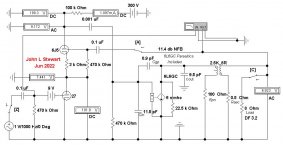
For these tests the OPT model has been corrected. For the OPT I've used the specs of a Hammond 125DSE.
That has resulted in a much better frequency response for the sim.
With no NFB full output from the 2A3 requires less than a volt at the input. Freq Response is 3 db down at 10 Hz & 30 KHz.
A few db of NFB doubles the DF.
That has resulted in a much better frequency response for the sim.
With no NFB full output from the 2A3 requires less than a volt at the input. Freq Response is 3 db down at 10 Hz & 30 KHz.
A few db of NFB doubles the DF.
Attachments
@jhstewart9 Any comments you could offer on my post #15 above?
Of course, others are welcome to comment too.
Of course, others are welcome to comment too.
OK Charlie, the detailed data sheet covering the 6B5 you had posted on DIY a while back is very helpful. The plate family of the composite tube is included. From that it is easily seen that the loadline follows a path where the output section of the tube is always forward biased. That is completely opposite to what we normally see in audio design & appears to offer an advantage. When properly driven & loaded the tube will never clip on positive going waveforms. OTOH there might be a problem at the other end of the loadline on large signals.
While running the tests of ~20 years ago I found the composite tube to assume the mu of the driving triode when the input plate was connected to the output plate. At the time I didn’t go further with my look at this kind of tube, there were as always other things that needed attention. My income work depended on a lot of travel.
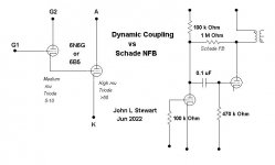
The attachment shews as best as I can the difference between the connexion of the plate as compared to Schade NFB that you had wondered about. At this late date I’m kinda wishing I’d bought a couple of those tubes for a closer look. 🙂
While running the tests of ~20 years ago I found the composite tube to assume the mu of the driving triode when the input plate was connected to the output plate. At the time I didn’t go further with my look at this kind of tube, there were as always other things that needed attention. My income work depended on a lot of travel.
The attachment shews as best as I can the difference between the connexion of the plate as compared to Schade NFB that you had wondered about. At this late date I’m kinda wishing I’d bought a couple of those tubes for a closer look. 🙂
Attachments
Thanks John, so does the direct (no resistor) connection between the plates of the 6N6G sections add negative feedback? Or would you characterize it in some other way?OK Charlie, the detailed data sheet covering the 6B5 you had posted on DIY a while back is very helpful. The plate family of the composite tube is included. From that it is easily seen that the loadline follows a path where the output section of the tube is always forward biased. That is completely opposite to what we normally see in audio design & appears to offer an advantage. When properly driven & loaded the tube will never clip on positive going waveforms. OTOH there might be a problem at the other end of the loadline on large signals.
While running the tests of ~20 years ago I found the composite tube to assume the mu of the driving triode when the input plate was connected to the output plate. At the time I didn’t go further with my look at this kind of tube, there were as always other things that needed attention. My income work depended on a lot of travel.
The attachment shews as best as I can the difference between the connexion of the plate as compared to Schade NFB that you had wondered about. At this late date I’m kinda wishing I’d bought a couple of those tubes for a closer look. 🙂
Sonically, it emulates what I would expect from the addition of NFB.
It certainly is a unique tube. I'm afraid I only have a limited grasp of the technical details which are described in great detail in the original Triad 6B5 data sheet.
Thanks John, so does the direct (no resistor) connection between the plates of the 6N6G sections add negative feedback? Or would you characterize it in some other way?
----------------------------------------------------------------------------
It is NFB in the sense that the composite tube becomes a triode of mu equal to its input triode.
When mu goes down plate resistance also goes down & DF improves a lot.
Sonically, it emulates what I would expect from the addition of NFB.
--------------------------------------
You would experience a decrease in volume as well as a tightening of the low frequencies due to better damping.
Sounds like you are more than a bit interested in the ins & outs of electronics & these audio amps.
With a simple scope & signal generator you could discover for yourself what is happening in the circuit as mods are made.
Good test equipment, both new & used has never been cheaper. 🙂 👍
- Home
- Amplifiers
- Tubes / Valves
- 27 In Cascode Front End