bequerel said:Thanks, Kevin!
I have a stash of 01a tubes, some with brass base and tip. 😎
Now I only need the iron, chassis, pot, and, and...😉
I know that feeling only too well.... 😉
- So do I... 
I have decided to try this preamp too, with 26 tubes, as I have a few...and most parts, but need iron...
Arne K
I have decided to try this preamp too, with 26 tubes, as I have a few...and most parts, but need iron...
Arne K
Key thing to keep in mind with the 26/01A/112A/12A is that they are all quite microphonic and also a little prone to hum pick up from external fields due to their high RP.
Both of these issues are fairly easy to live with, in terms of microphonics there are two possible approaches:
One - mount the 26's on a well isolated subchassis with significant mass. (Say a KG or so)
Two - Build a heavy and very solid pre-amplifier chassis and make sure it is well decoupled from its surroundings. High mass aluminum plate with spikes for example.
Best of both worlds - combine both..
Note that mine is built with no isolation whatsoever (it started out as a cheap experiment) but I have added mass where possible and use foculpods to isolate it from the very heavy rack it sits in. Microphonics have not been a big problem.
To reduce hum pick up electrostatic shields around the tubes are a must, not pretty for sure, but some vintage radio types are suitable and will do the job. I am using brass foil shields grounded to the chassis and this works fine.
The power transformer should not be anywhere near either of the output transformers - you will be surprised how audible even small amounts of magnetically induced hum can be..
The second most critical component after the output transformer in terms of sound quality is the coupling cap. Don't scrimp here..
Enhancements: You can reduce the value of the 499K grid resistor to 249K with a 100K pot, and this reduces the influence of gas induced grid current on the operating point. You can go even further if you are using a 50K pot and use a 121K resistor. (Scale coupling cap value as necessary for flat bass response.)
I have also added 1K grid stopper resistors right at the tube sockets as insurance against all of the other changes I made. Frankly in most instances with these low transconductance tubes their not really needed - just insurance..
Use a pair of 9V batteries (one per channel) for bias - note that you loose the ability to tweak the operating point if you choose this route unless you make the plate supply variable. (Do not exceed 180V if you do this.)
Read the article carefully if you have not done so.
I am quite pleased with the result, and continue to evolve the design. I have tried to share the knowledge gained since I wrote the article on this thread. Don't hesitate to ask questions.
Black's work on negative feedback was not well known to the fellows designing these small signal tubes so they were made to be as linear as the art permitted at the time - one of the reasons why they work so well in this kind of circuit.
Back in the day when 26s were used - how did they keep them quiet enough for radio use? Was it just for battery radios?
I have a few 26s sitting on the shelf that I will use someday - but I think I will have to go with a two chassis solution!
I have a few 26s sitting on the shelf that I will use someday - but I think I will have to go with a two chassis solution!
The 26 was actually used in early AC sets. A considerable amount of the voltage gain was provided by transformers. Chassis were heavy, and the bandwidth of the speakers (horns) was very limited so most of the noise did not get through. Expectations were low compared to today as well which probably helped.
Anyone try a 56 instead? From what i can tell the valves are nearly identical but for the 56's slightly bigger gain and some minor circuit adjustments...
26 or 76 have microphonic difficulties but if you're willing to absorb the investment in bum tubes, it certainly is worth it
Hi Burnedfingers,
None of these are mercury types, which can act somewhat like regulators, as internal resistance drops with increasing current.
I cannot however hear a difference between the 5R4,5y3,5AR4,5U4,5V4 and others I cave tried in the same circuit.
None of these are mercury types, which can act somewhat like regulators, as internal resistance drops with increasing current.
Hello
It is my fist participation in this forum.
Please look my 26 preamplifier. It is not ready now but sound like an angel and have zero noise and very low microphony.
In Filament i use Tentlabs modules made to 26.
Plate choke + 200H installed inside chassis
Output cap Mundorf silver supreme
Vintage Amphenol UX sockets decoupled from chassis
All Aluminum chassis
Separated power supply tube rectifier and tube regulated
Separated power transformers for Tentlabs
Shield wire in input
Fixed bias with 9V battery
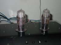
For last and for me the most important thing i made in this project is shield the tubes (see picture)
Upgrades that i will do in near future
Replace the Alps pot with Attenuator
Replace the power supply with a new version with AZ1 rectifier paper in oil filter cap with CLCLC.
Salvado
Portugal
It is my fist participation in this forum.
Please look my 26 preamplifier. It is not ready now but sound like an angel and have zero noise and very low microphony.
In Filament i use Tentlabs modules made to 26.
Plate choke + 200H installed inside chassis
Output cap Mundorf silver supreme
Vintage Amphenol UX sockets decoupled from chassis
All Aluminum chassis
Separated power supply tube rectifier and tube regulated
Separated power transformers for Tentlabs
Shield wire in input
Fixed bias with 9V battery
For last and for me the most important thing i made in this project is shield the tubes (see picture)
Upgrades that i will do in near future
Replace the Alps pot with Attenuator
Replace the power supply with a new version with AZ1 rectifier paper in oil filter cap with CLCLC.
Salvado
Portugal
Attachments
- Status
- Not open for further replies.
- Home
- Amplifiers
- Tubes / Valves
- 26 preamp