Do you have specific reasons, or “probably not” just means your hunch? The rating is based on proof test at certain voltage of dielectric barrier. If you stack these in series, the voltage applied across dielectric scales same way that capacitors in series gain the cumulative voltages of the individual caps.
That's three times the potential to the environment more than the mfr intended.
There's just no way to know.
Last edited:
Well, I could just make it and see if it works. I have a bunch of them. If I had a
variable 25kV lab supply one could do an experiment to see where it breaks down.
You could make a lab voltage multiplier circuit. The breakdown results could vary with
the ambient conditions, and mounting.
Last edited:
If a DC-DC converter is rated 5kV. Can putting 3 in series give me 15kV?
Assuming all are on the same low-volt supply: the third one has 15KV from end of HV to the common LV supply. This may exceed ratings.
Oh, I see. 5V to 5V to 5V.
I though they were 5KV output modules and you would *stack* them to get 5K+5KV+5KV= 15KV output. (Why? I don't know.)
Yes, _if_ the isolation is exactly 1Gohm the 15KV splits to 5KV each.
But the "1G" is merely "typical". It surely can't be exact. No variation is cited.
Assume your three "1G" parts are really 1.0G 1.1G 1.2G. Across a 15KV jump the high-R one gets 1.2G/3.3G of 15KV or 5,454V, 1% over spec. Top drawing. That seems "safe" but the assumptions are shaky.
But not just the modules. PCB leaks. Maybe not as bad as the lower drawing, (one module on 100Meg PCB the others on perfect PCB), but it could be trouble.
How long does this test run? Someone above mentioned a 9V battery. This obviously has to be in a 15KV insulator (thick plexiglas, ceramic soap dish), and won't last forever. But a low-power (perhaps intermittent) head-amp might run many many hours.
Attachments
Thanks, PRR for the sketch - it is exactly how I meant it to work. I searched on internet and could not find another example of someone trying to do this. Seems obvious but maybe not. I just realized that I want a linear MC78L05 at the last stage so replace the last one with a 5v to 9v to have some headroom for the dropout in the linear regulator. If one makes the PCB with great care as to track spacing and keeping these HV isolators far from other stuff it should be ok. Yes, inside insulated box to prevent arcing, shock, etc.
This is for a diagnostic device to monitor how well the DSI is working over a period of days to weeks. Originally, I thought it was for a day or so in which case the 9v battery would be fine. The voltage of the spark plug is high but the protection circuit takes a lot of the sting out (post 1) as it has a plasma spark gap (150v) followed by 470k resistor then a set of diode clamps. Technically, the voltage reaching the voltage monitor should be less than 1.2v after the diode clamp.
This is for a diagnostic device to monitor how well the DSI is working over a period of days to weeks. Originally, I thought it was for a day or so in which case the 9v battery would be fine. The voltage of the spark plug is high but the protection circuit takes a lot of the sting out (post 1) as it has a plasma spark gap (150v) followed by 470k resistor then a set of diode clamps. Technically, the voltage reaching the voltage monitor should be less than 1.2v after the diode clamp.
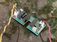
Well I just tested it with a stack of 3kV (10Gohm) rated Murata CMR0505SA3C DC-DC’s. I added recommended 22uH and 100nF x7r, 2.2uF x7r, and 10uF tantalum on the output. The input has 1uF x7r and 22uH and 1uF x7r as a CLC filter to prevent back propagation of switch noise into the DC supply. Works like a champ - my isolation opamp continues to function well even during the sparking process.
Attachments
- Status
- This old topic is closed. If you want to reopen this topic, contact a moderator using the "Report Post" button.
- Home
- Source & Line
- Analog Line Level
- 25kV Isolated Opamp?