Hi Guys
The layouts were finished and ready to post back when I posted the schematic, but this forum does not allow compressed files.
In the mean time, I have not had time yet to get them posted to my own site, besides which, I don't know how to do that. My IT person will be helping me over the weekend...
There are other ways to lay out the circuit than the example of my first layout above. You could easily incorporate the bridge and main filters on a board with the output stage, then have a daughter board that carries the front end and plugs onto the power board. The advantage of such an arrangement is the short power paths for the output stage, with everything close to the filters. It is also suitable to dual-mono designs, where every channel has its own PT.
The basic split-board design is also conducive to trying different front-ends if you wish to experiment to hear what sounds best, etc.
Note also that the same board and circuit as above can be taken down in voltage and used for lower power. The large output stage will exhibit lower THD than single devices, with much reduced gain wobble around the crossover point. At lower voltages, one can run higher idle currents and expand the class-A region, too. Lower voltage operation is also more adaptable to lower load impedances.
Have fun
Kevin O'Connor
I really like designs that have 2ch amplifiers on a single board, side-by-side, with the complete power supply (rectifier and caps) in the middle. Like Rod Elliott's P3A and some of the ASKA designs. I suppose it wouldn't be practical with an amplifier this powerful due to heatsinking requirements.
Struth, would you recommend CRC/CLC topology for this amp or not?
Struth, would you recommend CRC/CLC topology for this amp or not?
Hi Guys
Few amplifier circuits require CRC or CLC filtering in their supply lines. The ones that _require_ it have poor PSRR to begin with, and often draw nearly constant current. Properly designed circuits have good PSRR and may draw constant current or have quite dynamic current draw. As intended, the design here will have a modest idle current and much higher peak currents - almost 8A for 500Wpk into 8R. The design here can be biased quite hot if one wants to experiment with thermal tracking AND has assured ample heat sinking and/or fan cooling to move the heat away.
As an example, the coil sizes used by Pass in many of his supplies is in the milliHenrie range. Suppose it is "large" at 100mH. Suppose this works against a 10mF cap. The reduction of 100Hz ripple is by a factor of 4, so 4Vac ripple reduces to 1Vac. This is 6db as far as audibility goes, so "a bit quieter". The actual coil values tend to be much smaller, so the possible hum reduction is proportionally less. The DC resistance of the coil will introduce some sag under loading, just as using low-value resistors will do.
In lower current situations, such as supplies for tube amps, CRC and CLC are good options. L can be larger without the part becoming cumbersome, and any voltage losses incurred by DCR is more tolerable.
In the CRC and CLC cases, the added DCR creates a low-pass filter that helps keep noise out of the amplifier, and also helps to limit initial charge currents for the caps.
In amps like the Lin or Blameless, one rail is connected to constant current sources, which inherently provide a clean output. Their output is assured to be clean by filtering the DC path to the control element (base of a BJT, gate of a jfet or mosfet). This rail does not need decoupling.
The other rail is used as a reference for the VAS, so must be a good AC ground. This rail needs decoupling for the front end circuitry.
From all of the above, you then see why there are three local filter caps on the board layout instead of four.
Yes, Ranchu, lower-power amps with fewer output devices are much easier to put onto a single board. That has many advantages when your power requirements allow it, as interwiring is reduced to controllable trace placements, and ground routing can be optimised by the designer - only beneficial if he/she knows what they are doing.
It is not important in a stereo or multi-channel single-board layout - or even in a discreet channel board layout - for the PSU to be in the middle. Often, it is better to have the supply to one side or corner of the chassis to isolate its noise and to confine the mains wiring to an area where signals are not present. In any arrangement, it is more important that there be significant local filtering near each output stage for transient current requirements. This also holds the supply lines at a low impedance even if the rectifier and main filters are far away, which helps maintain amplifier stability.
Have fun
Kevin O'Connor
Last edited:
Hi Kevin,
I have a question about rail voltage. What is different about this design that allows for +80V rails when the Honey Badger and DX Blame MKIII can't?
Thanks, Terry
I have a question about rail voltage. What is different about this design that allows for +80V rails when the Honey Badger and DX Blame MKIII can't?
Thanks, Terry
Last edited:
Hi Guys
The design here was intended to meet Brlmat's power requirement of 250 into 8R. That sets what the supply rails need to be at load, then you allow for a bit of sag from idle to arrive at idle rail voltages. You also want to assure that the 250W can be attained despite device variations and small fluctuations of the mains.
Most high-power amps operate with 80-100V rails, although 100V rails might require going to higher than 100V rated caps. There are economic considerations and in certain lines of capacitor, 100V is the limit, as for the Nichicon HE-series specified for the filters and most electrolytics on the PA card. All the electrolytics should be from this line, and because of voltage/value limitations in that line, the small filters can have a range of values to suit the actual voltages you decide to use and also what is available to you. It is best to try to stick with the diameters shown on the layout, as the larger Ds have longer life in this line.
The designed power output of the other designs you mention is not quite as high as here. There are compromises in all three designs. The DX and HB are both EF2 outputs, where here we are using EF3. The HB has a cascoded front end like ours, so will have better PSRR than the DX. DX adds some diode-blocked filtering to make up for this. The HB has just three pairs of outputs, which is okay for most hifi, but Brlmat wants to run the amp hard. The DX has five pairs, which helps reduce gain wobble contributed by the output stage itself, but does nothing to reduce VAS loading, as the predriver in ours does.
As for adjustments, HB uses fixed Rs soldered in as required to set bias and to set the front end current, then includes a DC offset pot. DX has a bias adjustment per usual, just as we do. I've never found a need for an offset pot in any modified-Lin type circuit, whereas comp-diff circuits sometimes do need it.
How much voltage you can apply to a given circuit is limited by the devices used to build it, and to a lesser extent the voltage ratings of available caps. In our circuit, every BJT that sees the full +/- supply is rated for 230V or more.
Similarly, any cap that can see the full +/- swing must be rated 250V or higher. Caps like the input or feedback cap only see a few volts, so can be the largest value you can find that fits the footprint (C2,4).
In the VAS positions, one can sub the popular TO-225 types (BDs, MJE340/350 etc) but you have to rotate them on the board (ECB instead of BCE).
Have fun
Kevin O'Connor
Thanks again Struth. I have gone ahead and ordered some of the Panasonic TS-UP 100V caps you recommended earlier in this thread. Mouser were out of stock of the 6800uF variants so I order 16 of the 4700uF ones instead. I'm undecided whether to configure these as one single bank for both channels (i.e. 8 caps per rail) or 4 caps / ch / rail instead. Each MkIII board has 2000uF of local filtering per rail in my build.
Panasonic have a few lines that go up to 160V, including the HC series. the 3300u cap in this line (part number EETHC2C332LJ, 2000h @ 105C, ripple current @ 120hz = 3.3Arms) sells for A$9.10 is quantities 10+
Granted, you would need a lot of them (32+?) for adequate filtering; however, still works out significantly less expensive than a few large cans.
Hi guys! I am a little on hold with this project as my budget became 0 overnight but i shall resume as soon as possible.
Ranchu, i think i'll go for two banks, each for a channel. I don't sincerely think it makes any difference whether you make one bank or two, although i am not sure.
Ranchu, i think i'll go for two banks, each for a channel. I don't sincerely think it makes any difference whether you make one bank or two, although i am not sure.
brlmat, when you come to buy your caps have a look at the datasheet for the Panasonic TS-UP. I found the 4700uF offered better C/$ and Arms ripple / C compared with the 6800uF version.
I think I'll do the same: seperate bank per channel (yielding ~19mF per rail in my case). Given the number of caps I've decided against mounting them on power supply PCBs.
I plan to going to tie them together with cable ties in a 4x4 configuration, stick them to a sheet of plexiglass with silicone sealant, and connect the terminals using bus bars made from strips of 1-2mm copper sheet cut to size. The plexi sheet will sit over the transformer and bolt to the case using standoffs made from 3mm ID steel tubing cut to length.
Should give a good mechanical and electrical connecting without costing much (I have most of the materials and hardware lying around the workshop).
Hi guys!
I have some questions regarding the caps on this amp.
What's the voltage rating of C6? It only says on the schematic that is should be an 22u electrolytic but no voltage rating.
What should i base my judgement on when i choose a cap for C4? It says there 2m2-4m7. How big should it be and why?
It says there that 82u caps can be between 47u and 270u, yet i haven't found any 82u caps. Can someone please explain?
C2 is a BP (bipolar, right?). Yet there's a positive and negative terminal? What's the deal here?
Also, only 16 caps? I am surprised. I have seen many amps with lots and lots of caps.
Plus, i am attaching the part list. I sincerely recommend you double check it too. The parts that don't have a value written next to are the ones i couldn't find on the schematic. Kevin says that because of numerous modifications the part numbers got a little messed up.
Attachments
Can you repost the schematic? Also may I suggest you update your first post with everything from Struth (with due credit and a link to his website, naturally).
Here's the schematic. I'll try to update the first post.
Btw: for filtering the main rails. I have the big caps but i know that after them you usually put some smaller ones. Are these simple electrolytics? What value should one use? I also read that you can increase filtering by putting a mains rated caps across each diode in a rectifying bridge. Does this help that much?
Btw: for filtering the main rails. I have the big caps but i know that after them you usually put some smaller ones. Are these simple electrolytics? What value should one use? I also read that you can increase filtering by putting a mains rated caps across each diode in a rectifying bridge. Does this help that much?
Attachments
Last edited:
C6 has the bias voltage across it, ~3.6Vdc
you could use a 5V or 6V electrolytic, but I would use >=16V since these seem to have better parameters. A 22uF 35V is very small.
C4 combines with R15 as an RC, that rolls off the LF gain of the amplifier.
It should be set lower than the input filter to minimise the voltage that can appear across it.
82uF is a E12 series value. Very few retailers stock E12 values.
Use 100uF or 150uF or 220uF or ....
Similarly C9 & 13 could be 1mF instead of 820uF.
C2 combines with R2 (47k, or an E96 value that is close) to form the High Pass Input filter and also blocks DC from the input.
The 22uF & 47k5 sets the F-1dB frequency to ~ 0.3Hz.
This is extremely low for an audio amplifier.
You could raise this by a factor of 10 to 50 (3Hz to 15Hz) using a 2u2F to 470nF film cap to block the DC and let through all audio frequencies.
Using a big electrolytic here seems to have gained nothing.
Q15 to Q24 (10 devices) draw big and very variable currents from the supply rails. One pair of 100nF decoupling capacitors for 10 devices seems inadequate.
One 100nF to 220nF (HF decoupling) for each of those 10 devices, i.e. 10 Ceramic caps and 2pair of 1mF as MF decoupling would be more suitable.
Last edited:
Hi Guys
Just to emphasise the point:
All the electrolytics were selected form the Nichicon HE-series.
Where DS spec'd 47uF for the filters for the CCSs, as a 100V HE part you won't find it. Ina that voltage range, there is 56u then 82u both in the same size can, so in this case 82u is the standard value.
Go to Digikey or to Mouser and look up the Nichican HE series. Their data sheet shows the life expectancy for given voltage ratings and can diameters. The 18mm parts are 10khrs, so I chose the highest values at 100V in 18mm as the three main filters for the PA card.
At the low-voltage end of their range, where you select the feedback electro, 6v3 caps are rated at just 4khrs at 6.3mm dia, 6khrs at 8mm and 100mm, then at 12.5mm dia and larger they are 8khrs. From 16V up, 5khrs (6.3mm), 7khrs (8,10mm) 10khrs (12.5mm+). I tried to use sizes and/or voltages that gave longer life ratings.
Note these are 105C caps. Every 10C reduction of internal temp doubles the life. In most places on this board the caps will run more or less at room temp, so you could easily use 85C caps without issue. I just prefer the HEs wherever I can apply them.
The input bipolar cap should be as large a value as you can fit so that it has no real bearing on input shaping. Same goes for the feedback cap, which is not a bipolar but should be an HE chosen for the largest value that will fit. To make these caps small enough to cause an audio-range rolloff would incur serious low frequency THD.
As Brlmat has noted, there are a few geographic resistor and cap designations skipped over. That happened as the design morphed from something else to what it is.
The main filters for the power supply were originally spec'd as Panasonic TS series 6m8 - 100V. These are a 3khr cap with two snap mount pins of standard spacing. This is an 85C part.
The TUPs Ranchu mentioned have multiple pins and come in larger diameters. 6m8 in that range is rated at 6.6A just like the TS, but is only rated to 2khrs at 85C. You can get 12mF 100V 85C 2kHr 8.65A, or go to 105C and get from 10mF (8.82A) up to 27mF (12.53A).
There are tonnes of cap options that will work for the main filters.
As discussed previously, the main filters should be chosen to exceed the ripple requirement, then you can bump the value up further for improved reliability and reduced ripple voltage. I'm putting together a BOM and brief description of the design to go up on my site, along with the gerbers etc.
If you do not need 250W-8R or do not require hard use capability, you can reduce the supply rails and/or the filter cap requirements. As you go down in voltage there are more cap options.
One bank of filters vs one per channel: the latter is potentially more reliable inasmuch as the rectifier only has to handle on channel worth of current. In either case, it is important to use correct wiring to eliminate rectification noise in the supply lines to each channel.
Have fun
Kevin O'Connor
Hi Guys
The board layout here is only one of many that are possible for the circuit, as described in a previous post.
Local filtering is often left off of PA cards and that is a mistake. The supply lines carry large varying currents that can induce signal into sensitive areas, and can also act as an antenna ofr RF noise. This is why you often see 100nF caps on the PA card where the power comes in. These caps short out the RF antenna, but otherwise do little for transient current requirements of the amplifier. When the designer addresses the latter issue, you see 100uF or so as typical values.
The design here uses 820uF per rail (C13,14) and this is ample for the design requirement considering the main filter capacitance recommended earlier.
Since part of the original design requirement was a no-clip circuit, low frequency limiting is a part of that card - not the PA - where there is room for a polypropylene input cap. Polyester should be avoid due to its H3 characteristic.
Have fun
Kevin O'Connor
This explanation does not seem right to me.............The input bipolar cap should be as large a value as you can fit so that it has no real bearing on input shaping. Same goes for the feedback cap, which is not a bipolar but should be an HE chosen for the largest value that will fit. To make these caps small enough to cause an audio-range rolloff would incur serious low frequency THD..........
What rolloff of the audio is required to have
I have stated F-1dB ~3Hz. You have an F-3dB ~0.15Hzno real bearing on input shaping
Are we looking for minimal phase (how much) at 20Hz or 10Hz or some other?
Or is it more important to have flat frequency response within +0-0.1dB from 10Hz to 20Hz and upwards, or at some other frequencies or at some other attenuation value?
Hi Guys
Andrew, see Self's measurements in any of his books regarding LF THD caused by electrolytics. Having a too-low value E cap results in thousands of times the LF THD present in the rest of the amplifier. Electrolytics should never be used to define audio range frequency limits.
As you know, to be flat to about 0.1db in the pass band requires a rolloff one decade away.
Part of the original design requirement is to have very low THD without requiring a ridiculously complex or tweaky circuit.
Another part of the requirement is to have a limiter so the amp does not clip and blow tweeters. The no-clip circuit is a plug-on board so builders can add it or not. In any case, because this board is part of the original spec, it carries the components that shape the input LF response, leaving the PA to simply be "wide band" in that regard but not uselessly DC responsive.
Have fun
Kevin O'Connor
yes, D.Self and others have confirmed.....Andrew, see Self's measurements in any of his books regarding LF THD caused by electrolytics. Having a too-low value E cap results in thousands of times the LF THD present in the rest of the amplifier. Electrolytics should never be used to define audio range frequency limits.
yes, a decade away would be around F-3dB=2Hz, your 22uF is more than a hundred times lower.As you know, to be flat to about 0.1db in the pass band requires a rolloff one decade away.
but the circuit shows an electrolytic defining the High pass at the Input, surely that is "tweaky". A film cap that has relatively low distortion and nearer ideal parameters would meet this low THD requirement and still meet the 0.1dB flatness in the audioband.Part of the original design requirement is to have very low THD without requiring a ridiculously complex or tweaky circuit.
I did not see a limiter.Another part of the requirement is to have a limiter so the amp does not clip and blow tweeters. The no-clip circuit is a plug-on board so builders can add it or not. In any case, because this board is part of the original spec, it carries the components that shape the input LF response, leaving the PA to simply be "wide band" in that regard but not uselessly DC responsive.
Hi Guys
Andrew, try reading the whole thread. There are no electrolytics defining the bandwidth to be used.
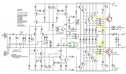
There is a parts equivalence error on the schemo in the notes under the circuit name, should read:
93 - MJL21193 or MJL1302A
94 - MJL21194 or MJL3281A
Have fun
Kevin O'Connor
Andrew, try reading the whole thread. There are no electrolytics defining the bandwidth to be used.
There is a parts equivalence error on the schemo in the notes under the circuit name, should read:
93 - MJL21193 or MJL1302A
94 - MJL21194 or MJL3281A
Have fun
Kevin O'Connor
- Status
- Not open for further replies.
- Home
- Amplifiers
- Solid State
- 250w 8ohm amplifier