If you can live with just treble and bass controls then Rod Elliott has a nice design, with the benefit that boards are available so you can actually build it and not dream about it.
Hi-Fi Preamplifier
I'm building P88, which is a similar design but without the treble and bass controls.
Hi-Fi Preamplifier
I'm building P88, which is a similar design but without the treble and bass controls.
I am currently designing the mono boards. It's a bit difficult as i tend to go lower than 1 mm in track width without realizing. I'll post it when i finish.
As for the controls, i'd rather stick to the 10 band eq. I may go as low as 7 band if i consider it's to difficult to design.
As for the controls, i'd rather stick to the 10 band eq. I may go as low as 7 band if i consider it's to difficult to design.
Hi Guys
Brlmat, for your EQ, trace width is not that important as the currents are very tiny. 1mm= 0.039" The default track width in most PCB software is 0.016" (16 thousands of an inch, ie 16 thou), or 0.4mm. Note that such a track on a 2-ounce copper board can carry 1.8A with a 10C rise.
Try to keep the pads large enough to take resoldering. Also, make sure the clearance within holes and vias allows solder to flow. Typically 7-thou is good enough for this - the drill size is 0.007" larger than the pin size.
Default board designs are double-sided. There is no economy in single-sided unless you live on Pluto.
Also keep in mind that most graphic EQ boards are made up as a "sandwich". One board carries the pots while a second carries the active circuitry and the two plug together using whatever flavour of pin-headers and receptacles you like. Depending on the gyrators used and the allowable spacing between the stereo pots, you can do everything on one board. Also, it may make a difference if you are trying to use sliders, for the truly graphic look, or are content to use rotary controls.
Most of the main board layout is done. Will post soon.
Have fun
Kevin O'Connor
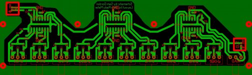
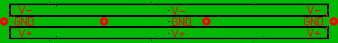
I finished the board. I only have to triple check it. The pads are big and the traces are big so anyone can etch the boards, even if they trace them by hand. In the mono configuration you can build the board as shown. I did not deal with supplying power as many of you wanted but I made it easier for those who want more than one mono eq board. It also has a ground plane around it so interference is minimised. To supply power you have to build a power strip. To ve more exact, etch a power strip. Everything is bolted togheter so it's easy to parallel an infinite number of boards. As I said, I have to triple check everything so there's no mistake it the layout. For the ICs I recommend soldering a socket.
More on this later! What about the layout for the blameless?
More on this later! What about the layout for the blameless?
I finally finished and checked the layout!
I'd tell you something about the THD performance or so but i sincerely have no idea how to simulate the schematic.
The board is mono but you can stack them, thus having all the connections close together making wiring stereo pots easy.
You'll see that the supply connections are near each ic. I did this because it was much simpler to design and it also makes the boards easily stack-able. You bolt them together with 6 screws (M3) which also act as ground connections for the ground plane. The actual supply (+-15v) will be connected to the power strip and distributed further through long pins. I'll try to make a drawing. I hope you like it and is useful!
The gerber files are NOT mirrored!
Even though i checked it, i recommend double checking. You can use Gerber View to add both copper and silkscreen in order to simplify the job of checking the circuitry i you can't download the pictures.
Attachments
Also, do you guys know what's the gain of this amplifier? Around 44? Also, what's the sensitivity? 1Vrms to full power?
About stacking the eq boards, it should be like this:
_________________________________ <<power strip
_[]___||||__[]__||||__[]__||||__[]___ <<eq A
_[]___||||__[]__||||__[]__||||__[]___ <<eq B
|||| - the power delivery pins
[] - M3 screws
About stacking the eq boards, it should be like this:
_________________________________ <<power strip
_[]___||||__[]__||||__[]__||||__[]___ <<eq A
_[]___||||__[]__||||__[]__||||__[]___ <<eq B
|||| - the power delivery pins
[] - M3 screws
Last edited:
Struth said 3 or 4 days ago that he could do it. Impressions about the eq layout? It's the first layout I ever made.
i think it looks nice.Struth said 3 or 4 days ago that he could do it. Impressions about the eq layout? It's the first layout I ever made.
allot better than i could ever do!
Hey guys, how much supply filtering do i need? Also, the caps should be rated for 100 or more vdc, right?
Regarding the PCB, i started working on the amp. I doubt i'll finish it so I'd still count on someone else doing it.
Regarding the PCB, i started working on the amp. I doubt i'll finish it so I'd still count on someone else doing it.
The EQ boards look great to me (no doubt other members will comment on the technical aspects).
I like Struth's suggestion of separate boards for the pots and circuitry. That way you can use dual gang pots to control both stereo channels from the one pot, run a ribbon cable(s) running to the other board, and have more flexibility on how to lay out the components
I like Struth's suggestion of separate boards for the pots and circuitry. That way you can use dual gang pots to control both stereo channels from the one pot, run a ribbon cable(s) running to the other board, and have more flexibility on how to lay out the components
True for some. I'll have all my small signal stuff in the front of the amp, the amps left and right, transformer in the center, protections and output in the back of the case so this is the kind of board that suits me best. One can also do the whole two boards thing by etching another potentiometer board and wiring to the boards I designed; the shield can be connected to the front part of the ground plane if that's the problem.
So regarding the filtering... how much do I need? I think 100v caps are a must but how much capacitance?
So regarding the filtering... how much do I need? I think 100v caps are a must but how much capacitance?
Last edited:
The rule of thumb I am working to is 5000uF per ampere. For the power you are targeting that's about 2.5A and 12,500uF per channel/rail.
From what I've seen, you can safely get by with 80V caps with rails up to ~63VDC but anything over that and you'd want 100V caps.
Guys, shouldn't R47, R48, R49 be more like 5w resistors? At full power, R48 will dissipate around 3w, R49 around 2w and R47 depending on the wire used for the coil ( I'd rather use 1,5mm wire instead of the said 0, 65mm).
So, shouldn't one use 5w resistors for these 3? Can I build the coil as the one in the diyAB amp? 16-18turns on 12-15mm tube?
So, shouldn't one use 5w resistors for these 3? Can I build the coil as the one in the diyAB amp? 16-18turns on 12-15mm tube?
Hi Guys
The PA board is nearly done. There will be a variation of it afterwards.
Brlmat, regarding the EQ circuit: Your pot symbol threw me off at first but I see you used the standard bax circuit only for one control per section. You could have used two per section, as 1+6,2+7,3+8, etc. Each paiur of bands is then far enough apart that they do not conflict using the same opamp - half as many opamps then. How you did it will work just the same but requires more power.
Do you have a dedicated low-volt supply? If not, then discrete regulators will be needed to drop from +/-90V down to opamp rails. This could be broken into two cascaded regs to split the dissipation and improve filtering.
For the main filter caps, you can begin at many points. The nominal RMS current per channel is 5.6A, so nearly 12A stereo. The ripple current rating of the filters should be about three times this value, so 18A. Looking at the Panasonic TS-series caps, 100V, 85C, 3khr life at full temp, the largest value is 6m8 with a 6.6A ripple rating. Three of these per rail would be the minimum filtering with respect to ripple. Some guides use a 6x factor, so there would be five to six of these caps per rail. If the caps you choose have lower ripple ratings, you'll have to use more of them.
(For reference, the cap quoted here is Panasonic ECO-S2AP682EA, Digikey part# P6113-ND, 35mmD 50mmH 10mmLS)
If you then look at ripple voltage, this is relate to the capacitance and always looks disappointing unless you have tenths of Farads. Fortunately, the PA has excellent PSRR, so normal ripple values are perfectly acceptable. The old rule of thumb of 2mF/A would suggest 24mF/rail based on RMS current, or about 35mF/rail based on peak. For the power hoped for here, and the hard use you intend, it is better to aim high in capacitance. This has the benefit that you end up using multiple filters rather than singles, and then the frequency response of the supply is improved.
There is a small amount of on-board filtering in my PA board design. This helps with transients and also helps with the supply impedance issues. The ones chosen are Nichicon HE-series with a 10khr life rating at 105C. I've designed the no-clip as a plug-in board, so you don't have to use it or build it if you don't want it.
The board could have been smaller if all the Rs were sized for 1/4W only. I used a foot print that fits the MRS25F 600mW 1% metal films, or equiv. Metal film is preferred; you can use carbon if you want 5-10x as much THD. Board size at the moment is about 7x3.5", 178 x 89mm. The driver heat sink space is sized to accept the largest extruded PC mountable type available: Aavid 529801B2500G, available in taller heights, but as designated exhibits about 5C/W.
Have fun
Kevin O'Connor
Hi Struth
For the sake of argument, if you were to use 8 of the Panasonic caps you reference in conjunction with your design, would it be better to organaise them as 2 banks of 4 or 4 banks of 2 (individual bank per channel)?
Regards
For the sake of argument, if you were to use 8 of the Panasonic caps you reference in conjunction with your design, would it be better to organaise them as 2 banks of 4 or 4 banks of 2 (individual bank per channel)?
Regards
Hi Guys
A correction to some numbers above:
Because the amp pulls current from the rails alternately as half cycles, the RMS current for each rail is half what I listed above, so about 6Arms for both channels together driving 8R, or for one channel driving doubled power into 4R.
This reduces the total ripple capability required for the filter caps to 18Arms for both channels combined, assuming you only want to drive 8R loads. If you want to accommodate higher power than 250W into 4R per channel, then the currents go up as expected.
I tend to use the original pessimistic or conservative numbers when designing my supplies, as this leads to longer capacitor life, a stiffer supply with better transient holdup, and a supply with a better frequency response. It is perfectly acceptable and is standard practice to use the lower numbers for these calculations, with their lower capacitance number requirement.
The previous numbers would suggest 10-12 caps overall, 5-6 per rail. The acceptable numbers allow for half this quantity, say three per rail for stereo. This puts the minimum capacitance per rail at about 20mF. Personally I would go higher, especially if I wanted to push the amps hard as Brlmat does.
As a much earlier post of mine stated, it is best to have filtering as close to the amps as possible to aid stability and assure proper performance from the amplifiers. Ideally, one would run a dual-mono system. Most builders will use a common PT and main supply. In either case, the distributed filtering concepts shown in my books apply. Some filtering should be close to the rectifiers to absorb most of the "dirty" current from the rectifier. Each set of filters out from the rectifier can nominally exhibit cleaner currents such that the filter set closest to the PA will have pretty clean currents. So, a possible arrangement would be to place one pair with the rectifiers, and a pair beside each amp. More pairs in each position won't hurt anything except your budget.
Have fun
Kevin O'Connor
- Status
- Not open for further replies.
- Home
- Amplifiers
- Solid State
- 250w 8ohm amplifier