Hi Folks,
as i was surfing on internet to search for parts i came across to this cap (see the attached picture)
There is a 220uF for 58euro and 100uF for 28euro.
I think i saw these caps on some of the hi end stuff on the market but i can't remember where.
Anyways my doubt lays between using this cap on the coupling signal path on the ONO phono or usinghe Blakgate FK 220uF, which by the way is the FK series eventually the most indicated for coupling purposes?
I believe that a film cap would be better than an electrolytic in any case.
I don't know if anybody knows these caps and used them actually.
Thank you for the attention
Attachments
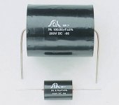
from the logo and by researching on google i think they are Solen cap, i don't know if i am right though!
Hi,
a polypropylene in lieu of an electrolytic for audio coupling must be better.
Do you really need 100uF/220uF?
or
what about a 220uF bipolar Panasonic paralleled with a 4.7uF 250V MKP? an affordable experiment that may turn out to give all you need/expect.
a polypropylene in lieu of an electrolytic for audio coupling must be better.
Do you really need 100uF/220uF?
or
what about a 220uF bipolar Panasonic paralleled with a 4.7uF 250V MKP? an affordable experiment that may turn out to give all you need/expect.
well.. i don't really need 220uF on the coupling path.
Just keep in mind that the question needs to be asked to Mr Pass, since he switched from the 10uF on the old version to 220uF on the XONO.
It can be seen on the simulation that a better low frequencies response is achieved this way.
I guess that your suggestion is inexpensive and thus can be tried on, but still, in order to gain a clear idea on what is better, I would still have to try this out against the the blackgate and the film cap.
I am wondering if anybody had a similar experience with these film caps or similar film caps and compared them to a good electrolytic or something.
Anyways Andrew thank you for your idea.
Hi Stefano
Built the MM part of it several years ago and found it ok but not spectacular. The MC part i really dislike. It has a lot of flexibility with the variable gain but once you choose a cart you wouldn't have much use for setting gain and no matter how you look at coupling caps it just has too many of those. If i had to use an active MC step-up device i would rather use a parallel common cathode fet fed by an entirely separate high quality (Jung?) regulator.
Of course 220uF is completely unnecesary in this circuit. 10uF is more than enough and if you decide to use MC carts only you can go even lower by increasing the value of R20. It is set to 47k for compatibility with MM carts but can easily be increased to 100-200k. Alternatively you may want to investigate a switching arrangement (relays?) which when switching from MM to MC will also connect another parallel input resistor.
Hi analog,
thank you very much for your instructive answer.
I am planning on using a nice shunt all fet PSU design.
I am also planning on using auricap caps on the RIAA network and PRP resistors....and other good stuff for the stage.
I don't like the idea of having multiple coupling caps on the signal path ether.
I got rid of the output coupling cap by adjusting the offset at the differential stage...so one less....but for the others: no possibilities to be eliminated.
I am planning on building only the stage MC (so NO MM) for a specific cart (Denon DL103) so no relays no switches for loading adjustments.
I am making researches on how to properly load a cartridge to obtain maximum performance, which by the way, if you have some useful links at hand, please go ahead and post it if you wish.
Therefore, since no MM stage will be included, you told on the previous post i can lower the 220uF and increase the resistor R20 up to 100k or more and that would fix the bottom end response.
I am eventually going to replace it by a 10uF auricap film cap or less....i will explore the different options with the simulator.
But how about the other 220uF coupling cap on the MC stage? Can this be lowered as well accordingly to your experience?
And one last question: about the 220uF coupling cap for the feedback network on the MC stage: can this be lowered? does the quality of this cap affect the sound of the phono stage?
thank you very much for the attention.
To tell the truth i don't know if there is much point in having the second stage (Q15) at all. The only real purpose behind it is to invert phase. At the time i had a fet MC step-up i found a single common source stage was more than enough (gain around x25). And it sounded better to me than a cascode. The value of C37 is high as it may need to work into 5k load if J2 is shorted. If you avoid J2 then C37 can be many times lower. Same is true for the feedback cap C27. It's the minimalist's nightmare 🙂 And i don't think it was designed by Mr Pass.
yes, you are right.
The Ono wan't designed by NP as far as I know but by Colburn.
I read lots of good impression on the sound of the ONO all over the forum but i do agree with you that it doesn't seem to be as minimilastis as it should ...in the good sense...of course.
I made couple of adjustments on the RIAA network and got a little more precise RIAA equalization.
Also, I lowered all 3 coupling caps down to 10uF and frequency response seems to resent just a little bit by this modification at least on the bottom end response but i guess i can live better with a 4Hz cut frequency but a good film cap rather than 3.5Hz and 3 electrolytic on the signal path 🙂 .
Your point on the Inverting stage Q15 is interesting and i will reflect on this and see whether i can take it out or not.
Although I like to think that it is not elegant for me to have an inverted sine wave at the output, I do think that the less the better in certain cases as for example the inverter at the output stage.....off!!!
Thank you again for the good points you brought in this thread.
Iirc the original Ono was criticised mostly for the bass. It may be the reason why all coupling caps are over the top in the X. I'll be very interested in your build and subjective assessment. Mine was certainly not as ambitious and i only used mundane parts: cheap metal film resistors, Wima MKP and Cerafine caps. The end result was highly listenable and musical but not having any outstanding qualities.
Well Cerafine are actually good electrolytic caps, aren't they?
I was thinking on using them on the PSU.
Actually undecided to use Cerafine or Standard Blackgates...but BG for the PSU are too much expensive.
Since i am planning on using a 200mA shunt design, in order to get good ripple rejection's performance, I need at least 2500-3000uF cap each rail per each channel.
This would head up too much the final price if BG would be used.
I am undecided.
Can you tell me your impression on the Cerafine?
Have you had any opportunity to compare the Cerafine on the PSU against Panasonic FC or Muse or other caps?
I think that your idea to remove Q15 is good as that stage brings with it more complexity and 2 more coupling capacitors to just invert the phase of the signal(I don't see any other advantage on using it).
I am just wondering if having an inverted phase might be harmful, but as far as i am concerned, as long as both channels have the same phase, everything should be fine.
humm....interesting.....i will think through.
Absolute phase is audible in a good system. Apparently some listeners are more sensitive than others as it doesn't bother me too much on most recordings. It is certainly easy to do the inversion at the speakers end but if your other sources are non-inverted this is not practical. From what i know, lots of recordings, especially digital are not always in correct phase. Probably the most elegant place to invert phase is in a dac, so if you consider absolute phase important you can always adjust your digital sources there.
Capacitor discussions are too personal and system specific to be of much value. It seems the best compromise between price and quality for me is Nichicon Gold Tune (KG).
Capacitor discussions are too personal and system specific to be of much value. It seems the best compromise between price and quality for me is Nichicon Gold Tune (KG).
right!
You can re-adjust the phase at the speakers as well as at the cartridge wiring.
Another thing i am thinking and i don't know if you had any experience with this or nor but on the current mirror of the MM stage, a led diode is used as voltage reference.
I know that leds are fairly stable in temperature and fairly low noise, but i know that a very good IC voltage reference would hit the spot in terms of stability and noise.
I am wondering if a led is preferable because is cheaper or because it sounds better.
analog_sa said:To tell the truth i don't know if there is much point in having the second stage (Q15) at all. The only real purpose behind it is to invert phase. At the time i had a fet MC step-up i found a single common source stage was more than enough (gain around x25). And it sounded better to me than a cascode. The value of C37 is high as it may need to work into 5k load if J2 is shorted. If you avoid J2 then C37 can be many times lower. Same is true for the feedback cap C27. It's the minimalist's nightmare 🙂 And i don't think it was designed by Mr Pass.
I have asked to Mr. Pass if he thinks Q15 can be removed and he replied that if I do that, the phono would stop working.
This is interesting.
I don't understand why it would stop.
All in all it just look like a 1X inverting stage.
Does anybody have any idea of why that stage is required? besides that phase can be swapped when the cartridge is wired up!?
Have to agree with Mr Pass 🙂 If you simply remove Q15 it will stop working. Maybe he was in one of his jovial moods.
Sorry, just kidding. I mean if you literally remove the fet but leave everything else in place it won't work very well. But it won't stop altogether either. Maybe that's what Mr Pass meant. Did you explain you intended bypassing the stage, rather than simply removing Q15?
I don't know if i was able to explain myself or not.
All I know is that even if i would just remove Q15 the output at R40 will be coupled through 2 caps (C37/19) and then across R42 there would be the difference of 25V minus the output of the MC stage the and the output of the MC would be coupled into the MM through the couping cap C10.
The only thing is that the current on R4 will flow though (??!) maybe this could cause some problems..not sure though.
Even so simulating the circuit, again, even just taking Q15 off still shows a working circuit.
anyways....i don't know if i was able to explain my self to mr pass or not...i guess not...or maybe there is a reason we don't catch of why the stage won't work
😕
As I understand the circuit those 2 caps (C37/19) build a voltage divider and are part of a feedback loop, their non-linearities should largely cancel out. I am not at all shure whether different caps in this position make much of a difference, or whether bulky SCR MKPs sound any better than the much smaller electrolytics. Personally I would look elsewhere for improvements.
Also, I think I read somewhere that electrolytic caps have high distortion at low frequencies (D. Self ) and increasing their value might resolve this issue or rather move the frequency range down, hence the 220 µF. On top of that, low frequency phase shift is supposedly audible and to counter that you would need a low 3dB turnover frequency of ca 0.6 Hz.
my 2 cents.
Also, I think I read somewhere that electrolytic caps have high distortion at low frequencies (D. Self
) and increasing their value might resolve this issue or rather move the frequency range down, hence the 220 µF. On top of that, low frequency phase shift is supposedly audible and to counter that you would need a low 3dB turnover frequency of ca 0.6 Hz.my 2 cents.
- Status
- Not open for further replies.
- Home
- Amplifiers
- Pass Labs
- 220uF coupling cap for ono Film or BG?