Please
your preferred voltages for your 211 valve amp (not parallel)
example:
Volt Plate 950v
Volt grid -50
Amp plate 58ma
your preferred voltages for your 211 valve amp (not parallel)
example:
Volt Plate 950v
Volt grid -50
Amp plate 58ma
Load
Hi,
The example values give a loadline of around 12.5KOhms. The OPT will be tricky that way.
May be a 10KOhm line with same Eg, a bit higher current (65mA or so) and 974 Ep could work. The will put the THD figure a bit higher (not much though) but squeeze more power out.
Alternatively a 11K, 9.5K or even 20K loads could be used, as Lundahl makes transformers with that primary Z.
Post your results if you have any. I want to learn more about experiences of people operating 211s.
Cheers,
Rada
thanks so far but
thanks, based on an existing transformer (amp is built), just verying the -grid but keeping 950v as a referance what would be the ideal ma
thanks, based on an existing transformer (amp is built), just verying the -grid but keeping 950v as a referance what would be the ideal ma
Hi,
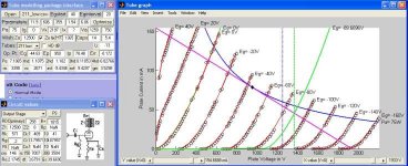
I am a beginner of this and I have never built an amplifier. I am just designing one with 211 tubes and model the tube behavior and parameters in Matlab. So take my comments as comments from somebody in the process of learning about tubes and amps. Don't go mod your big $$$ amplifier based on what I say!
Anyhow, after the safety advisory, with the Ep at 950 with a 12.5KOhm loadline and 58 to 59mA you must have an Eg aorund -50V and 100V of grid swing or so, and a B+ a bit higher than 1000V (assuming SE topology and >250Ohm primary DCR for the OPT).
Keeping the loadline slope, and Ep at 950 you could only go higher on Eg (closer to 0). If you go lower, the distortion figure will get worse unless you reduce B+ and allow less grid swing.
At 58mA you are still a bit far from the limit of the tube. Assuming you want to reduce a bit its life, you could put the grid up to -45V to get the operating point pretty much on top of the dissipation limit curve of 75W (that's the data I have from one of the many 211 datasheets and it may not represent your tube). The current will be around 78mA and your OPT may not take it.
Without doing a major mod of the B+ supply you will loose a bit of power and like 10V of grid swing. The distortion figures may improve though.
So I guess that between -50V/58mA to -45V/78mA you could go anywhere in the middle.
Hope this helps.
Rada.
PS: Is it a SE I assume? What OPT you used to build it? Thanks.
Attachments
- Status
- Not open for further replies.