Hello fellows DIYers,
I have been planning for a long time to build my dream set of speakers and this time I got the time, space and resources to finally do it.
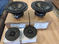
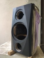
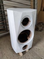
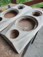
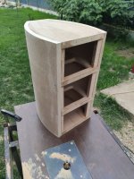
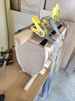
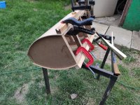
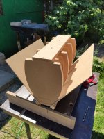
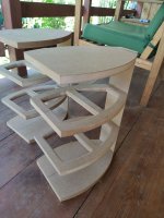
Doing a lot of research, with the goal of "best bang for the buck", I set my eyes on Jeff Bagby's TRIBUTES. For the enclosures I got some inspiration from SF and some Aliexpress clones. They will sit near the back wall so I decided to put the port on the front. They are almost ready, I'm waiting for the veneer and I'm working on the crossovers.
This is where I got so far, feel free to comment, critique, advise.
I have been planning for a long time to build my dream set of speakers and this time I got the time, space and resources to finally do it.
Doing a lot of research, with the goal of "best bang for the buck", I set my eyes on Jeff Bagby's TRIBUTES. For the enclosures I got some inspiration from SF and some Aliexpress clones. They will sit near the back wall so I decided to put the port on the front. They are almost ready, I'm waiting for the veneer and I'm working on the crossovers.
This is where I got so far, feel free to comment, critique, advise.
Attachments
-
 1623694389500.jpg109.1 KB · Views: 668
 -
 1623694389412.jpg86.1 KB · Views: 390
 -
 1623694389425.jpg130.1 KB · Views: 280
 -
 1623694389434.jpg142.3 KB · Views: 273
 -
 1623694389441.jpg161 KB · Views: 243
 -
 1623694389464.jpg204.1 KB · Views: 216
 -
 1623694389480.jpg173.6 KB · Views: 487
 -
 1623694389490.jpg172.1 KB · Views: 472
 -
 1623694389497.jpg184.1 KB · Views: 474
 -
 1623694389503.jpg174 KB · Views: 517

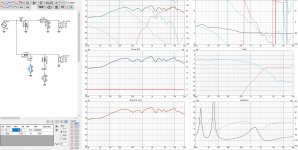
This is where I would appreciate some advices from you. I got my measurements in room, mostly from 45 cm with a 3.5 ms gating. Simulating the original TRIBUTES crossover, it doesn't fit to my enclosures, so I decided to go second order serial crossover.
I can upload my measurements if someone is interested in giving a hand with the crossovers.
Thank you,
Petru
I can upload my measurements if someone is interested in giving a hand with the crossovers.
Thank you,
Petru
Attachments
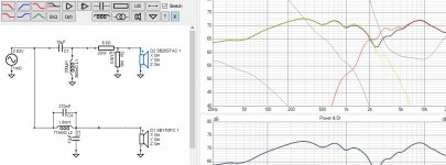
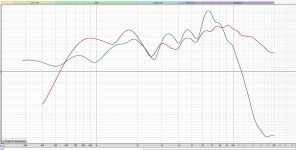
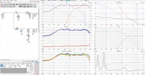
It is room response , see null above 150hz. I don't think I need more BSC
Attachments


Last edited:
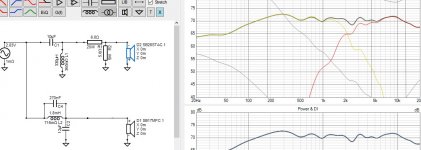
1-9 kHz needs to be lower in level.. Similar to or slightly lower than what you have at 700 Hz.
Last edited:
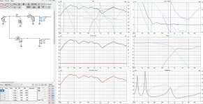
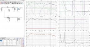
Hi, if possible follow the VituixCAD measurement guide and take as many quasi-anechoic off-axis measurements as you have time, if not full set of measurements. You'll see the power response and directivity which would help you to refine the crossover network further. From the phase graph it looks like vertical polars and power response is a mess, but this needs input by some more experienced designer, or full set of measurements. edit. phase seems to be ~45degrees at the crossover so not a biggie.
Other observation, treble doesn't seem optimal with peak below 10kHz and then drooping after that. Maybe a broad notch there and less attenuation with the L-pad? 🙂 Datasheet of the tweeter doesn't have bump at 10kHz, this might be a reflection in your measurement or feature of you current filters?
Other observation, treble doesn't seem optimal with peak below 10kHz and then drooping after that. Maybe a broad notch there and less attenuation with the L-pad? 🙂 Datasheet of the tweeter doesn't have bump at 10kHz, this might be a reflection in your measurement or feature of you current filters?
Last edited:
Thanks for your input. The bump in the tweeter (6k-12k), followed by the drop is due to uncalibrated mic, the tweeter , as you say, does not have that, so it should be flat.
Thank you.
What does that mean? How does that reflects on the crossover and the sound?phase seems to be ~45degrees at the crossover
Thank you.
If you change a component in the sim look at the individual phase responses, can yo get the phase to match (overlay each other) for both drivers around 2Khz or so in graph 1.
Doing this will lessen your 45 degree phase separation, its worth trying, and even if it doesn't help the frequency response much it may still improve imaging if you are into that.
Doing this will lessen your 45 degree phase separation, its worth trying, and even if it doesn't help the frequency response much it may still improve imaging if you are into that.
Yeah the phase difference of the drivers kind of direct the lobe either above or below the listening axis. In most practical cases I've seen in the sims the lobe goes below listening axis leaving a hole above the listening axis. Implication of this is that if you stand up there might be a hole in frequency response at crossover. This is why some speakers have the tweeter below woofer, to have the hole below listening axis so that FR is more even when standing up. On the other hand my smoothest sims have had the driver phases track each other very closely at the crossover but this depends somewhat on your acoustic system, the enclosure and transducer spacing and sizes. Important takeaway is that you can't see any of this in the simulator with axial measurement only.
You can play with this stuff in VituixCAD pretty easily:
Start a new project, add another driver and add high and low pass filters. These are "ideal" drivers with flat frequency response. Then start diffraction simulator from the tools menu, feed both drivers with "realistic" data, for example pretend making a 1" tweeter and 5" woofer with some realistic sized baffle. Or use your own speaker dimensions and driver sizes. Play with driver spacing, crossover slopes and frequencies and see what the Vertical polars (directivity window, bottom left in the VCAD sixpack) does in respect to the driver phases in the phases window. Be sure to turn on "In room response" right clicking "Power and DI" window. You'll notice many things playing with this kind of stuff, for example how dramatic effect baffle diffraction can have. I can't say if this is good or bad, just a feature you can exploit or avoid in your design, when you know it.
I encourage to take time and take vertical and horizontal measurements on the real speaker you have built. With the axial data only there is infinite ways to make the response nice but only handful are better than all the rest. With the handful, you'll able to discern them in simulator and if you want try them all and hear if any of them is better than the others 😉 For example what ruins or makes "the imaging" or is there any difference.
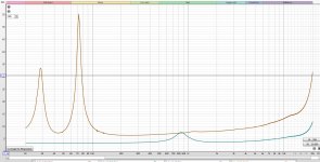
Attached is some simple example, ideal drivers on some simulated baffle. ~45 degree phase difference at crossover. FR and power responses are not too bad, but the "main lobe" at crossover is below listening axis and hole above.
Have fun!🙂
You can play with this stuff in VituixCAD pretty easily:
Start a new project, add another driver and add high and low pass filters. These are "ideal" drivers with flat frequency response. Then start diffraction simulator from the tools menu, feed both drivers with "realistic" data, for example pretend making a 1" tweeter and 5" woofer with some realistic sized baffle. Or use your own speaker dimensions and driver sizes. Play with driver spacing, crossover slopes and frequencies and see what the Vertical polars (directivity window, bottom left in the VCAD sixpack) does in respect to the driver phases in the phases window. Be sure to turn on "In room response" right clicking "Power and DI" window. You'll notice many things playing with this kind of stuff, for example how dramatic effect baffle diffraction can have. I can't say if this is good or bad, just a feature you can exploit or avoid in your design, when you know it.
I encourage to take time and take vertical and horizontal measurements on the real speaker you have built. With the axial data only there is infinite ways to make the response nice but only handful are better than all the rest. With the handful, you'll able to discern them in simulator and if you want try them all and hear if any of them is better than the others 😉 For example what ruins or makes "the imaging" or is there any difference.
Attached is some simple example, ideal drivers on some simulated baffle. ~45 degree phase difference at crossover. FR and power responses are not too bad, but the "main lobe" at crossover is below listening axis and hole above.
Have fun!🙂
Attachments

Last edited:
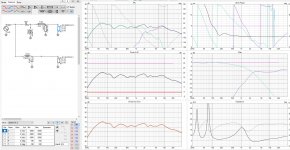
I'm not sure if the phase itself is too important, I've been using the phase window as an useful indicator while tuning a crossover. Pay close attention in the simulator to listening window frequency response and Power response, these approximate the sound you'll hear in reality much more accurately than the axial response. If you don't get the proper measurement set I suggest prepare few different XO designs and prototype them both. After listening determine what needs to be done, which one is better and what to tweak (by ear).
I found a pair of designs for your SB17MFC35-8 woofer:
SB17MFC35-8 x2 + D2606-9220 MTM Passive Crossover Design - Madisound Speaker PDF Library
SBAcoustics-61-MFC
The first on is an MTM, so you need to convert the bass filter values. Double coil and resistor values, halve capacitor values. Both employ a notch, probably around 5kHz. Troels' design is for time aligned baffle, so you usually change the second order tweeter to third order for flat baffle.
Your original design is a bit iffy. The 270nF tank notch on the bass filter will cause a direct short at high frequency when also flowing through the bigger 12uF capacitor. Bad practise.
Just a thought.
What does 1.8mH, 10uf and 0.3mH look like on the bass and for the tweeter come down on inductance a bit .22mH and make it third order with another 8.2uF after the inductor. Your idea to measure would give a more predictable result that's for sure.
What does 1.8mH, 10uf and 0.3mH look like on the bass and for the tweeter come down on inductance a bit .22mH and make it third order with another 8.2uF after the inductor. Your idea to measure would give a more predictable result that's for sure.
You can't expect steep rolloff on a second order filter with a 6". But the breakup is a worry.
Troels has opened up this 4th order SB17NRXC35-8 design. The woofer can't be much different from yours.
SBAcoustics-61-NRXC
Troels has opened up this 4th order SB17NRXC35-8 design. The woofer can't be much different from yours.
SBAcoustics-61-NRXC
Try to increase the gate to 7-8ms and measuring distance to 1m by rearranging the measurement setup. Your measurement resolution is quite, ehh, low with 3.5ms and acoustic sum at <0.5m won't be the same as at -say- 2m. In addition, you could perform a measurement including front wall and floor bounce with the speaker in listening position, just to evaluate the summing and cancelling. Then you will know better what you are listening at later.I have to do more measurements, I will do that this weekend.
- Home
- Loudspeakers
- Multi-Way
- 2 way SB17MFC+SB26STAC pic heavy