I can't tell what the final cross-over is for these drivers, any one know?
AFAIK the project evolved into this speaker:
Non Commercial 2 Way Standmount Speaker Project
Dissi, we have missed you. Where have you been? 🙂
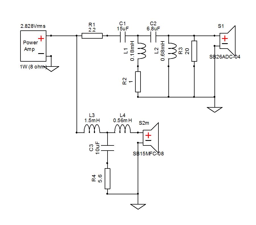
Blatent error there, surely? Tweeter capacitors in the wrong order. A Child of Ten can see that.
Blatent error there, surely? Tweeter capacitors in the wrong order. A Child of Ten can see that.
Blatent error there, surely? Tweeter capacitors in the wrong order. A Child of Ten can see that.
I can't.
Is the image accurate?
Hi, System7,
How it going?
You beat me too it, as I don't think your post arrived when i started typing, and probably had a tea break as well, which meant I had missed your response.
The original looks nice, and the graphs look good to me, I am sure it works well.
How it going?
You beat me too it, as I don't think your post arrived when i started typing, and probably had a tea break as well, which meant I had missed your response.
The original looks nice, and the graphs look good to me, I am sure it works well.
Capacitors could be the wrong way round, i agree as typically that's how it works out with tweeter Xovers.
Who knows , it could be a subtlety with this design. Ideally it would be nice to see graphs and a phase switch to see null.
Maybe Dissi knows if it is a simple error or not ?
Who knows , it could be a subtlety with this design. Ideally it would be nice to see graphs and a phase switch to see null.
Maybe Dissi knows if it is a simple error or not ?
I followed the link and have seen the graphs now.
The capacitors may be fitted that way in an attempt to knock the 2K bump down a bit more.
The capacitors may be fitted that way in an attempt to knock the 2K bump down a bit more.
Last edited:
Reverse order of capacitors isn't necessarily an error, even Zaph did that in his ZRT design. As you say it's a mean to prevent a huge impedance peak below the crossover frequency. But one has to be very careful, since the impedance quickly goes too low without a significant series resistor. 🙂
I did try it in a sim and it makes it worse at the 2K point.
System7 has spotted the obvious mistake, swap the cap positions in the given circuit.
System7 has spotted the obvious mistake, swap the cap positions in the given circuit.
TBH, I would trust my good friend Dissi far more than speaker genius Mr.Zaph or speaker genius Mr. Troels Gravesen.
My speaker design is based in unforgiving Mathematics rather than Audio Voo-Doo and Snake Oil. I say this with Irony. 🙂
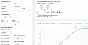
RF Tools | LC Filter Design Tool
I rest my case.
My speaker design is based in unforgiving Mathematics rather than Audio Voo-Doo and Snake Oil. I say this with Irony. 🙂
RF Tools | LC Filter Design Tool
I rest my case.
Attachments
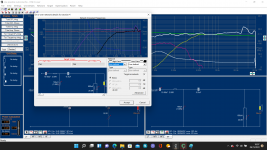
It doesn't look too bad to me. I happened to have some measurements of the sister 26CAC tweeter (basically identical) taken for a commercial project a year ago. It was a compact MTM, but baffle width isn't far off (6mm difference), so notwithstanding some changes in diffraction & loading mostly in the 1KHz - 2KHz region, it should be vaguely near.
Blue = raw on-baffle. Red with the above 4th order electrical high pass, level padding & damping resistor. Green indicates a nominal 4th order Bessel slope, 83.5dB, 2.25KHz nominal, which it's tracking in this instance quite well. Impedance isn't as well-damped at Fs as I'd prefer. Electrical transfer function looks reasonable also. Case rests, as they say, since this is based on hard data, notwithstanding some modest variation.
Blue = raw on-baffle. Red with the above 4th order electrical high pass, level padding & damping resistor. Green indicates a nominal 4th order Bessel slope, 83.5dB, 2.25KHz nominal, which it's tracking in this instance quite well. Impedance isn't as well-damped at Fs as I'd prefer. Electrical transfer function looks reasonable also. Case rests, as they say, since this is based on hard data, notwithstanding some modest variation.
Attachments
Last edited:
Snap!!
I also opened up my logbook. On the two occasions I have used the SB acoustics tweeter it has always been smaller value first, but the logbook shows they got to being equal a few times as iterations were tried, and on one occasion larger first was tried.
Basically they are all variations, and even if a design uses textbook LR, Bessel, Butterworth, Chebyshev, M derived whatever, i can guarantee that once i we start tuning or playing with a design the original alignment to a textbook filter goes.
Your filter designer is nice, I like it.
It works with fixed impedance, which we are not typically dealing with here on the majority of occasions, which you fully understand.
I imagine you have old textbooks with graphs and tables of how to work filter for 600 ohm or 50 ohm applications. 🙂
Keep up the good work.
Attachments
That's interesting -first time I've seen a screenshot from Fine X-over. The PCD7 sim I posted above was using the measured driver impedance, same as yours; the image Steve added looks to be a pure electrical filter assuming a fixed load, but no doubt he'll confirm.
Either way, agreed: there doesn't look to be anything wrong with the electrical topology of the linked high-pass as far as I can make out.
Either way, agreed: there doesn't look to be anything wrong with the electrical topology of the linked high-pass as far as I can make out.
Last edited:
I should add, lest anyone notices: the acoustic transfer function graph I posted above has 'T29R' as a header, but the FR and impedance data used is from the 26CAC, as stated. I'd had PCD7 open for a different project this afternoon & forgot to change the tweeter title. Sorry for any confusion.
I agree, interesting discussion.
Does this x-over work roughly the same with SB26STAC-C000-4 tweeter?
Seems to be the same tweeter, but with a fabric dome.
Does this x-over work roughly the same with SB26STAC-C000-4 tweeter?
Seems to be the same tweeter, but with a fabric dome.
Sort of. So is the original tweeter referenced on this thread actually. The SB26STC-04 is an OEM fabric dome & basically the same as the 26STAC. With the filter under discussion ( https://www.diyaudio.com/forums/mul...2-standmount-speaker-project.html#post5826477 ) it works in a similar way, with roughly 4th order Bessel acoustic slope at roughly 2.25KHz. SPL is about 2.5dB - 3dB higher so would require some adjustment to the level padding. The values could stand a tweak too as the responses aren't precisely the same, but they're in the ballpark. You'd probably lose the R2 shunt, drop L2 a little & increase the value of R1 to trim output level as desired. That's looking at it purely independently, & based on a very quick & dirty sim though, so in practice you'd likely need to make further adjustments to get the system response & phasing where you want it based on the on-baffle measurements.
Last edited:

- Home
- Loudspeakers
- Multi-Way
- 2 Way SB15MFC-08 + SB26STC-04