Interesting!
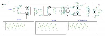
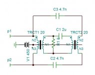
In diagram #1 there looks to be a problem with LF getting back into TRCT1 from the TR3 secondary. (needs another C in between the secondaries, like pic 2 has)
----------------------------------------
The 2nd diagram looks good I think.
TRCT2 enforces the same HF on both sides of TRCT1, ie same HF on both sides of the leakage L of TRCT1. Hopefully TRCT2 can be a small low turns HF xfmr, maybe Ferrite even.
There could be some phase issue in the frequency crossover region due to the C's? (although looks like the same phase shift reaches each side of TRCT2 if the coupling C's are impedance scaled, so no conflict there) I guess one has to pay attention to the leakage L in TRCT1 (plus the smaller leakage L of TRCT2) resonating with the coupling C's. And C1 has to be impedance scaled with C2 and C3 in series. (ie, turns ratio accounted for) So effectively the series leakage Ls are in parallel with the series effective coupling C's, forming a parallel resonant circuit. Where to put the resonance?
Last edited:
Poor wording fix for above.
Should read:
TRCT2 enforces the same turns ratio relative HF V on both sides of the leakage L of TRCT1 as would occur for an ideal xfmr case. (assuming both xfmrs having the same turns ratio)
-----------------------------------------------------
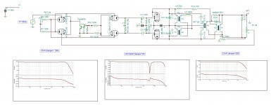
Seeing as the TRCT1 leakage L has no current thru it then, it would seem to effectively disappear. So possibly the parallel resonant circuit formed by the series Leakage L's and coupling Caps would now only be concerned with the lower leakage L of the TRCT2 HF xfmr. So the original OT (TRCT1) has had its resonance moved upwards to that of the TRCT2 HF xfmr. (well, likely depends on the effective coupling C's, which would likely be of similar reactance to the original TRCT1 leakage L at the HF crossover, to form the freq. crossover.) This would be VERY VERY GOOD!! as TRCT2 only need be a low turns xfmr to handle the HF portion.
TRCT2 enforces the same HF on both sides of TRCT1, ie same HF on both sides of the leakage L of TRCT1.
Should read:
TRCT2 enforces the same turns ratio relative HF V on both sides of the leakage L of TRCT1 as would occur for an ideal xfmr case. (assuming both xfmrs having the same turns ratio)
-----------------------------------------------------
Seeing as the TRCT1 leakage L has no current thru it then, it would seem to effectively disappear. So possibly the parallel resonant circuit formed by the series Leakage L's and coupling Caps would now only be concerned with the lower leakage L of the TRCT2 HF xfmr. So the original OT (TRCT1) has had its resonance moved upwards to that of the TRCT2 HF xfmr. (well, likely depends on the effective coupling C's, which would likely be of similar reactance to the original TRCT1 leakage L at the HF crossover, to form the freq. crossover.) This would be VERY VERY GOOD!! as TRCT2 only need be a low turns xfmr to handle the HF portion.
Last edited:
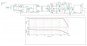
If the series effective scaled reactance of the coupling C's is equal to the TRCT1 leakage L at the HF crossover, then the parallel resonance from those C's and the HF TRCT2 leakage L would, I think, move the resonance up to the "mean" ( SQRT[f1 x f2] ) rather than all the way up to that of TRCT2 alone. Simulating the circuit could decide which occurs. Better performance still, but one would like to see the resulting OT resonance move -ALL- the way up to that of the HF TRCT2.
Last edited:
One problem that is still present in the 2nd design is the distributed C in the main OT primary is still shunting the HF. This can be fixed with some series HF inductors to the main primary (to TRCT1). These can be small (only relevant to the HF crossover) but will have to handle DC if placed in the tube plate paths.
Radio Designer's Handbook 4th ed. has general frequency divider solutions on pages 887 and 888. (also page 185)
Radio Designer's Handbook 4th ed. has general frequency divider solutions on pages 887 and 888. (also page 185)
Last edited:
I appreciate your interest to this subject . There are many aspects in your analysis that I didn't yet thought of . The most important issue is to eliminate the glitch due to low bias current which is essential to generate odd order harmonics of opposite phase at low power . In model simulating the main OPT L4 is P/S mutual inductor of 20khz performance OPT, L3 is the mutual inductor for P/P estimated to be 4 times the L4 . The circuit neglecting the capacitance of OPTs, provokes 2 resonances . The most important for the feasibility of this project is the series resonance due to primary inductance of the HFT and the 4.7nf capacitors that provokes notch in the audible range . This dimensions the values of the HFT . The second resonance as you pointed out is the parallel resonance due to L4 and linking capacitor C5. The notch can occur above the audible range, it can be tuned and dampened all to hear if higher frequency response 800khz with notch 40khz sounds better . The NFB is 10db.
Attachments
- Home
- Amplifiers
- Tubes / Valves
- 2 way OPT