I don't even know where to begin.
I have too much two way radio stuff.
I can't test the tubes or caps or inductors.
I already sent 23 lbs of tubes to a relative of mine who promptly put them in his shed with about another 400 lbs of tubes.
I attached a pic of a Motorola radio.
I have about 10+ of these or very similar models.
I have too much two way radio stuff.
I can't test the tubes or caps or inductors.
I already sent 23 lbs of tubes to a relative of mine who promptly put them in his shed with about another 400 lbs of tubes.
I attached a pic of a Motorola radio.
I have about 10+ of these or very similar models.
Attachments

Yeah, it's sad when well-designed hardware far outlives its original use. I'll bet those radios still work nearly as well as they ever did.
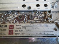
The Motorola "Motrac" radio product line appeared around 1960 and went through extensive design improvements and upgrades through the mid 1970's or so. The model number (e.g. "U63HHT") tells you the basic design series, whether it's a VHF (150 MHz band) or UHF (450 MHz band) radio, the number of channels (1, 2, or 4) and any special features. I think the earliest models used transistors only in the step-up switching power supply and audio output; later models were solid state everywhere but the transmitter power stages. They had a reputation for ruggedness and reliability, a very active used equipment market, and probably dominated the police/fire/public service market in the 1960's and early 70's.
They can be modified to work in the amateur bands but I don't know if they can meet current performance standards for the modern versions of their original application. The RF power tubes (2E26, 5894, and 6907; though I think some of these were marked with Motorola house numbers) and their sockets may have some value to folks building tube-type audio power amplifiers. The RF cavity filters, antenna switching relays, and the later solid state receivers, may be useful subassemblies for somebody building custom radio hardware in the UHF or VHF ranges. The chassis (look at those heatsinks!) can probably be re-purposed by anybody with access to modest metalworking tools.
Dale
We still have customers using low band (43.10 Mhz) HHT's. New FCC narrowband mandates doesnt apply to low band. Quite a few running 100 watts. Some running 25-30 off the exciter. Best two way radio ever built.
We still have customers using low band (43.10 Mhz) HHT's. New FCC narrowband mandates doesnt apply to low band. Quite a few running 100 watts. Some running 25-30 off the exciter. Best two way radio ever built.
Do you happen to know which models correspond to low band (43.10 MHz)?
Do you happen to know which models correspond to low band (43.10 MHz)?
Model number will have a 1 as third digit (i.e. U61,U71). VHF will be a 3. UHF will be a 4.

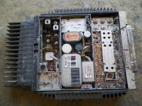
First photo: Could be a power supply assembly, possibly regulated, for something. It doesn't have the neatness and attention to detail I'd expect from a full-production product, so it may have been built for some special application, or even constructed locally to satisfy some unique requirement. Can you tell if the input was a mains voltage (110/220/208 VAC) or some DC voltage (6, 12, 24 or possibly 48 volts DC)? Off the seat of my pants I'd guess the transformer is good for at least 100 watts, possibly 200.. . . Also, what are these?
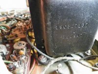
Second photo: Is this the same assy as Photo #1? Looks like a manufacturer's part number ("house number") stamped on a transformer end shell. This is likely a spec number from the equipment manufacturer (Motorola, RCA, etc) not the company that wound the transformer. Unless you can find the number in some old documentation or parts list, it doesn't tell you anything.
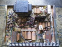
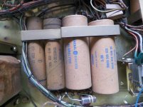
Third photo: Electrolytic capacitors with cardboard insulating sleeves. Obviously used in vacuum tube circuits. Based on the age of the equipment alone, I'd do some testing and bake-in before using them in a project that mattered. After going through appropriate tests and conditioning they may be of interest to somebody doing restoration and repairs on tube-type electronic equipment (of any type), and wanting to retain the "all original components" classification.
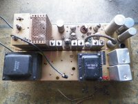
Fourth and fifth photos: Power strip, and either transmitter strip, or exciter strip, from some radio model in the GE "Progress Line" circa late 1950's. I don't see an electromechanical "vibrator" on the power strip so this may be a line-operated power supply for a base station. (Or are there some TO-36 or TO-3 transistors inside the chassis?) 100 watts or less for each of the transformers. (Why two of them?) I don't recall what the rectangular aluminum cans are. If it's some variation of a 2E26 inside the tube cage, it's an exciter; if the tube is a 6146 variant it's a full transmitter.
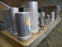
Sixth photo: Chassis-mount electrolytic capacitors. Same comments as third photo.
- Status
- Not open for further replies.