Koinichiwa,
A way in which I can see this work is to have a LF optimised transformer which can have high leakage inductance and thus very low parasitic primary capcitance and to use the second transformer in parafeed with a small, high quality core (Nickel etc...)and your favourite wire. That might be interesting...
Another option is double up the output stages and give each it's own OPT.... ;-)
Sayonara
Brian said:Can a power amp be built with two output transformers per channel? A big one optimized for accurate bass going to the woofer, and a small one optimized for clear and sweet mids and treble going to the wide range driver.
A way in which I can see this work is to have a LF optimised transformer which can have high leakage inductance and thus very low parasitic primary capcitance and to use the second transformer in parafeed with a small, high quality core (Nickel etc...)and your favourite wire. That might be interesting...
Another option is double up the output stages and give each it's own OPT.... ;-)
Sayonara
1 1/2 OTs per channel
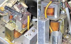
The snippet of a Grundig map shows 1 1/2 OPTs per channel with a common bass channel (i also have a Motorola amp with a similar scheme). The HF OPTs are quite small, the common one dramatically larger.
dave
BTW: Labtec just got a patent which -- as much as i can tell -- is essentially this scheme (but SS with no OPTs).
Attachments
Koinichiwa,
Well, a few things here. These schematics do interesting things. They are early "Sub/Sat" systems. The circuit works by having one channel inverted both in the drive to the output valve and at the output transformer. This makes the Amp still provide the correct polarity, but the anodes now operate out of phase, just like a PP Amp.
So, if you use a big fat PP OPT for bass (and note that the transformers primary sections are ALWAYS bridged by a capacitor) and a small and skinnly lowish inductance Transformer for midrange/treble, voila, you have an active Sub/Sat system with 4 times the LF power and a series X-Over.
It is an interesting concept for a small "phrugalphiles" Valve System. Take a pair of cheap 300B's, a pair of Hammond 125SE outputs and a nice spare 5k A-A Z PP Transformer. Set the X-Over as it falls and drive your Lowthers or whatever of the small Transformers suitably mismatched to have low primary inductance.
Again, the principle can be applied to single channels using one large "bass" Opt and one small "treble" OPT....
Sayonara
planet10 said:I also have seen a number of inexpensive stereo amps which introduced a 3rd transformer which was used to drive a bass speaker, (snippet of the circuit trace below). I am still not completely comfortable with my understanding of what is happening here althou i have my suspicions. What happens if you leave off the bass speaker or leave out the big OPT completely?
Well, a few things here. These schematics do interesting things. They are early "Sub/Sat" systems. The circuit works by having one channel inverted both in the drive to the output valve and at the output transformer. This makes the Amp still provide the correct polarity, but the anodes now operate out of phase, just like a PP Amp.
So, if you use a big fat PP OPT for bass (and note that the transformers primary sections are ALWAYS bridged by a capacitor) and a small and skinnly lowish inductance Transformer for midrange/treble, voila, you have an active Sub/Sat system with 4 times the LF power and a series X-Over.
It is an interesting concept for a small "phrugalphiles" Valve System. Take a pair of cheap 300B's, a pair of Hammond 125SE outputs and a nice spare 5k A-A Z PP Transformer. Set the X-Over as it falls and drive your Lowthers or whatever of the small Transformers suitably mismatched to have low primary inductance.
Again, the principle can be applied to single channels using one large "bass" Opt and one small "treble" OPT....
Sayonara
Koinichiwa,
Well, lets just do this a little bit theoretically.
First, lets decide upon a sensible Crossover frequency for our 2 Transformer series arrangement. Lets say we stick to the classic 80Hz X-Over to a bass. Lets use a 300B and a lot of people tend to run 3K nominal impedance Transformers on a 300B.
So, what we really want is to calcualte a series crossover at 80Hz for a 3000 Ohm impedance, where the HF transformers primary inductance forms also the inductance for the highpass Filter. We then want to know what value capacitor we need in parallel to the LF transformer.
A spreadseet to calculate (among others) 1st order series X-Overs is here:
FRD Consortium Passive Crossover Design Calculator
Lets load this and punch in our numbers....
This suggests 3H primary inductance for our HF transformer (meaning we can use a large airgap and a small core) plus a 1.33uF Capacitor across the LF transformer.
IN FACT, we likely could even make an absolutely outstanding "Fullrange" output transformer by simply connectingthe two secondaries in series as well....
Anyway, this should give enough ideas for now.
Sayonara
Brian said:Kuei Yang Wang, thank You. These sound like good ideas. I will have to learn more about transformer design before I can implement them as I am still very much a beginner.
Well, lets just do this a little bit theoretically.
First, lets decide upon a sensible Crossover frequency for our 2 Transformer series arrangement. Lets say we stick to the classic 80Hz X-Over to a bass. Lets use a 300B and a lot of people tend to run 3K nominal impedance Transformers on a 300B.
So, what we really want is to calcualte a series crossover at 80Hz for a 3000 Ohm impedance, where the HF transformers primary inductance forms also the inductance for the highpass Filter. We then want to know what value capacitor we need in parallel to the LF transformer.
A spreadseet to calculate (among others) 1st order series X-Overs is here:
FRD Consortium Passive Crossover Design Calculator
Lets load this and punch in our numbers....
This suggests 3H primary inductance for our HF transformer (meaning we can use a large airgap and a small core) plus a 1.33uF Capacitor across the LF transformer.
IN FACT, we likely could even make an absolutely outstanding "Fullrange" output transformer by simply connectingthe two secondaries in series as well....
Anyway, this should give enough ideas for now.
Sayonara
Re: 1 1/2 OTs per channel
Dave,
This is interesting; it seems the two small xformers play a major role in providing the feedback to the cathodes at the input side, thereby defining the closed loop.
Where do the wires go to at the right bottom side? Or did I miss that diagram?
Jan Didden
planet10 said:The snippet of a Grundig map shows 1 1/2 OPTs per channel with a common bass channel (i also have a Motorola amp with a similar scheme). The HF OPTs are quite small, the common one dramatically larger.
dave
BTW: Labtec just got a patent which -- as much as i can tell -- is essentially this scheme (but SS with no OPTs).
Dave,
This is interesting; it seems the two small xformers play a major role in providing the feedback to the cathodes at the input side, thereby defining the closed loop.
Where do the wires go to at the right bottom side? Or did I miss that diagram?
Jan Didden
Re: Re: 1 1/2 OTs per channel
They go off to the speaker plug-ins. (I have the entire map if anyone wants it -- Grundig Werke Furth)
dave
janneman said:Where do the wires go to at the right bottom side? Or did I miss that diagram?
They go off to the speaker plug-ins. (I have the entire map if anyone wants it -- Grundig Werke Furth)
dave
Attachments

- Status
- This old topic is closed. If you want to reopen this topic, contact a moderator using the "Report Post" button.
- Home
- Amplifiers
- Tubes / Valves
- 2 OTs per channel?