Also it appears you have an unused secondary for your 5V supply. I would carefully (observing polarity/phase) parallel the two secondaries to increase the current available to your placid.
Using both the secondaries pair to power the Placid?
Yes - that doubles the current available to the supply. Just be careful to match phase looking at the diagram on the transformer.
Russ White;5174600 I would test it by removing it from the rest of the circuit and connecting the inputs to GND. [/QUOTE said:Do you mean connecting are the inputs from the B-III as shown?
Attachments
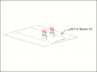
Do you mean connecting are the inputs from the B-III as shown?
Yes - while you are testing it separate from the other circuits.
With the inputs connected to Gnd as above and nothing connected, I got these measurement :
Left Output:
SE Output :
SE and Gnd : 319.8mV
Balance Output :
+ and Gnd : 157.2mV
- and Gnd : 165.2mV
Right Output :
SE Output :
SE and Gnd : 1.965V
Balance Output :
+ and Gnd : 0.979V
- and Gnd : 0.984V
I can't get my finger to the OPA1632.
Left Output:
SE Output :
SE and Gnd : 319.8mV
Balance Output :
+ and Gnd : 157.2mV
- and Gnd : 165.2mV
Right Output :
SE Output :
SE and Gnd : 1.965V
Balance Output :
+ and Gnd : 0.979V
- and Gnd : 0.984V
I can't get my finger to the OPA1632.
Last edited:
I tested the 2nd board and the result is similar to the 1st board :
Left Output:
SE Output :
SE and Gnd : 0.508V
Balance Output :
+ and Gnd : 255.2mV
- and Gnd : 252.4mV
Right Output :
SE Output :
SE and Gnd : 1.705V
Balance Output :
+ and Gnd : 0.854V
- and Gnd : 0.851V
Left Output:
SE Output :
SE and Gnd : 0.508V
Balance Output :
+ and Gnd : 255.2mV
- and Gnd : 252.4mV
Right Output :
SE Output :
SE and Gnd : 1.705V
Balance Output :
+ and Gnd : 0.854V
- and Gnd : 0.851V
With the inputs at ground the outputs should also be very near ground. So something is very wrong... are any of the IC's getting hot? You may need to double check the parts are all in the correct places on the IVY.
The parts should be in the correct places. The DAC has been singing for some years now prior to this. I finally got the tip of my fingers onto the ICs. Yes, they are hot but I do not know how hot should they really be.
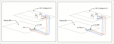
Another thing I did observed is that when I switched the Placid BP from the right output into the left input of the IVY-III and the left output to the right input, the voltage drop right to about 1.5V.
Another thing I did observed is that when I switched the Placid BP from the right output into the left input of the IVY-III and the left output to the right input, the voltage drop right to about 1.5V.
I am not sure what you mean here.... Why are you connecting the power supply to the signal inputs/outputs?
Very bad ....
Oooo! You're showing that you are taking the positive voltage output of the placid and inputting it to the negative power input of the IVY, and the negative placid supply output into the positive power input of the IVY 😱😱😱
That will probably destroy the OPA1632 !
Maybe the drawing will help me explain better,
Oooo! You're showing that you are taking the positive voltage output of the placid and inputting it to the negative power input of the IVY, and the negative placid supply output into the positive power input of the IVY 😱😱😱
That will probably destroy the OPA1632 !
Oh. ****. Shouldn't the Placid limits the current or voltage?
I don't know. Why not switch the plus & minus voltages to the the way they should be and see if it is ok? Nothing to loose at this point😉. Maybe the gods of audio will smile at you

It was already bad. I switched the power supply around to see if it works. It just got worse. It starts with the missing first second and then I put in another IVY which might have worsen it.
Last edited:
- Status
- Not open for further replies.
- Home
- More Vendors...
- Twisted Pear
- 2 ivy iii for B3