These are default drivers in vituixcad which makes them 8 ohms and resistive. I apologise for the ambiguity but I presumed the flat response of the upper woofer showed the direct substitution.As this whole thread is about 4 ohm woofers, I assume they are 4 ohm.
In fairness to others I should add that these two filter parts are tuned to work together.. as one driver departs the resistance cuts in. Looking at their behaviour when tuning shows that this circuit might be used to accommodate bumps in the baffle step or other resonances in that area as needed.
Last edited:

4 to 8 Ω is a factor of 2, You are stretching things with to bring in a voltage divider.
dave
When you put an 8 ohm resistor in series with a supposedly resistive 4 ohm woofer, 2/3 of the applied voltage drops across the resistor and 1/3, -9.54 dB, across the woofer.
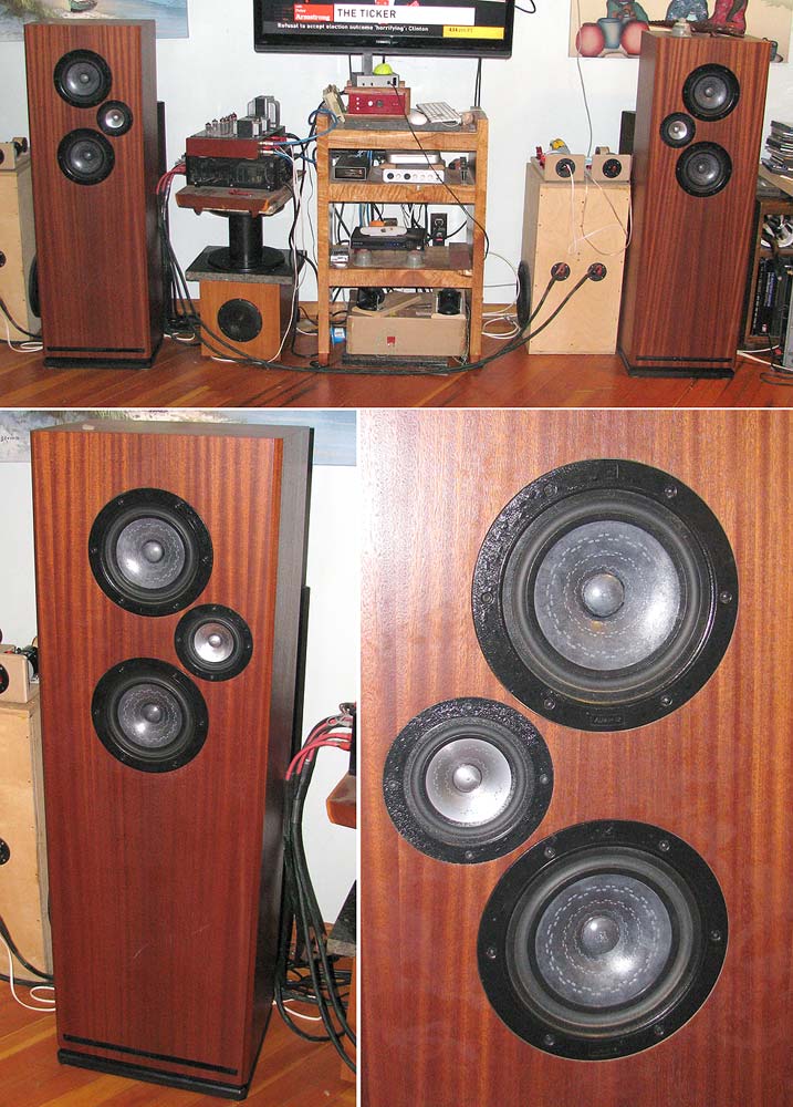
Anyway, AllenB just cleared it up: the woofers in post #6 are 8 ohm.
having a 'yard stick' of 250 Hz is just silly
it is not a yard stick, it is an example. And hard to make any comment about a loudspeaker you know nothing (except the XO frequency)
Not sure where the YES/NO comesn from, lots of examples of woofers in hifi loudspeakers XOing between 2-300 Hz. The common ones to a midrange (+ tweeter), substitute a midTweeter to eliminatethe problematic XO to tweeter. A commercial manufacturer will often factor cost of XO parts into the equation and increase the XO frequency.
And the loudspeaker is designed and quite a good one, XO is that low to maintain a less than quarterwave centre-to-centre. This eliminates some significant problems with having an XO. And it keeps approx half the 20-20k spectrium with the woofers and half with the midTweeter.
dave
I disagree about what LF gain a room needs or can support as being a general rule, even with typical speaker placement in regards to wall boundaries. Depending on acoustical loading and interaction with non-sealed enclosures, the resulting low end gain and extension can vary greatly.What is a facor of 3?
A parallel 2.5 way has 6 dB more output below the bottom XO point. For flat response they would have to be way out into a large room or outside.
Real rooms typically need 0-3 dB extra gain. 6dB is a facor of 4, 3dB and change in impedance are a factor of 2.
dave
Ported enclosures can have significant fluctuations in response to boundary loading. This can exaggerate certain room modes in either direction. Depending on how the enclosure volume is divided or shared, it changes LF impedance at specific frequencies which as a result affects power distribution among multiple LF drivers.
I've built a bunch of 2.5 and 3.5 way systems with varying multi driver acoustical gain. Anechoic sims help, but the real world LF response greatly depends on a myriad of variables. As one applicable general rule, .5 way systems with larger LF drivers and baffle surface areas can get away with closer boundary placement and/or LF gain. Most smaller systems with parallel multiple LF drivers suffer from excessive lower mids unless careful attention is paid to midbass phase relationship between both LF drivers.
Last edited:
Try figuring that phase relationship between all those... its like the chaos theory.
Last edited by a moderator: