Hi, I found a circuit on the web that looked ideal for just minor tweaking so that I can make a power amp using my EXICON 10N16 and 10P16 devices that I bought many years ago. I've not got round to building a power amp before and haven’t built an amp for some time (not since 2008) so seems a fun thing to do. It is 😀
LTSpice showed a couple of minor changes to the original circuit (mostly resistor values) and then in theory it should work fine.
I’ve built both channels and tested them. For music it sounds good, in fact very good, but ……
both channels have a low level 100Hz buzz that’s just audible when no music is playing, so must be a design problem. Oh dear.
Am I correct in thinking it’s due to very poor power supply rejection ratio ?
As an amp it has excellent potential so any help to fix the buzz is most appreciated.
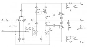
To help the gurus out there, attached is the schematic as built and a snap of the ‘scope trace.
Top trace is speaker output that shows the 100Hz 25mV signal (buzz). Exactly the same signal is present at both FET gates (Q7 & Q8) so I'm guessing there's something not quite right in the Q5/Q6 leg ?
Lower trace is positive supply. 36mV ripple on a +50Vdc rail.
Good correlation between the reservoir caps charging and the buzz spikes eh ?
Help! 😕 🙂

LTSpice showed a couple of minor changes to the original circuit (mostly resistor values) and then in theory it should work fine.
I’ve built both channels and tested them. For music it sounds good, in fact very good, but ……
both channels have a low level 100Hz buzz that’s just audible when no music is playing, so must be a design problem. Oh dear.
Am I correct in thinking it’s due to very poor power supply rejection ratio ?
As an amp it has excellent potential so any help to fix the buzz is most appreciated.
To help the gurus out there, attached is the schematic as built and a snap of the ‘scope trace.
Top trace is speaker output that shows the 100Hz 25mV signal (buzz). Exactly the same signal is present at both FET gates (Q7 & Q8) so I'm guessing there's something not quite right in the Q5/Q6 leg ?
Lower trace is positive supply. 36mV ripple on a +50Vdc rail.
Good correlation between the reservoir caps charging and the buzz spikes eh ?
Help! 😕 🙂
Attachments

A symmetrical amplifier as in the circuit you show doesn't care how much ripple there is on the rails. It is the ground points that are important. Ensure there is no loop and the input ground should be at the cross section of the main smoothing as should the loud speaker return.
Ah yes, good. I'm glad you said that. It explains why I didn't notice any buzzing when I did initial bench testing. I'll make some changes to the earthing later.
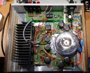
Here's a photo showing the current layout of the complete amp (still need to make a front panel though) so that anyone interested can see what's being discussed.
I thought it'd work OK but not so.
The earth reference is the green/yellow wire to the chassis bolt near the top right.
Speaker returns (both channels) via the single ground point near top left.
PSU and input signal ground are per channel which are the two ground points to the left of the transformer. Like I said, I thought it'd work but nope. A rewire on the way.
Any other advice about how to resolve the "buzz problem" is most welcome.
Attachments
Jon Snell is right - ground loops are the prime suspects. Can you try disconnecting the black links to chassis ground near the transformer? If that fixes it, replace them with low value resistors - 10 ohms or so.
I disconnected the chassis ground links as requested and unfortunately it made no difference.
I then removed all earthing such that each channel was floating. That means speaker "ground" is referenced only to the transformer secondary centre tap. That made no difference either.
Which leads me to think there must be a problem with the design perhaps?
I've measured voltages at various points of the circuit and checked recorded values against values LTSpice says to expect and all are reasonably close, so I have confidence that the PCBs I made are tracked correctly.
So, no nearer solving the issue as yet.
Where exactly is the signal ground connecting to the power ground? Can you try moving that point to different locations on the track? The current passing through the power supply filter capacitors should not be passing through that point.
First, turn off one of the channels, it doesn't matter which one, and try it then. If it works correctly, repeat the same thing with the other channel, but with the first channel turned off. And if both channels work correctly independently, but generate a hum when working together, then the problem is caused by ground loops.
That circuit looks very similar to an old Hitachi datasheet for lateral mosfets.
That circuit had hum also.
I decoupled the front end from the output mosfets with RC and that stopped it completely.
I put RC on both rails.
I used 100R and 100uf.
That circuit had hum also.
I decoupled the front end from the output mosfets with RC and that stopped it completely.
I put RC on both rails.
I used 100R and 100uf.
Many thanks for the replies .. I think I'm much closer now to the solution.
Basically, I have to confess I didn't really understand the difference between a signal ground and a power ground and as a result the amp PCB doesn't either.
SamAnytime
Your question prompted me to do research to understand exactly what you are getting at and I think I understand now which is why I now think the problem is indeed a PCB design issue.
Thank you..
syr
Thank you for the advice and reasoning.
I did as you said and can confirm the problem isn't due to a ground loop as such, almost certainly now it's an error in my PCB track implementation.
nigelwright7557
Thank you for your input.
It gave me a good idea what to research on the web to understand why my amp has a buzz problem now I have a better understanding of the difference between a signal and power ground.
I've modified the circuit in LTSpice (adding the 100uF and 100R CR circuit) to see the effect. Looks fine.
I'll modify the amp when I get a chance tomorrow and report back.
OK, reporting back as I said I'd do.
I've decoupled the input ground and the modification works a treat.
LTSpice suggests anything from 1uF and higher will do so I used 47uF 16V and 1/8W 120R because the two parts are physically small so easy to tuck away underneath each PCB and doesn't compromise the flat frequency response I was after.
Buzz gone, amp sounds very very good now. Many thanks for all the help.
- Status
- Not open for further replies.
- Home
- Amplifiers
- Solid State
- 1st power amp build .. 100Hz buzz .. hmmm