No, he is right.
But he did not tell you to connect pin 3 to ground through a big cap!
Do you understand that this breaks the circuit?
I understand that you want to connect the reference voltage to pin 3, but do it such a way that it does not impact the signal at pin 3. For instance, use a resistor large enough not to influence the filter impedances.
Jan
Many thanks for detailed explanation for a newbie like me!
He said:
Apparently it is obvious to him that a resistor is needed. But I didn't understand this until your explanation. So my new version 3.
I put R5 between pin 3 and virtual ground and made R3=R4=R5=500k. It's OK? And please check polarity of C1 and C4. Is it correct?
Thanks!
No, he is right.
But he did not tell you to connect pin 3 to ground through a big cap!
He said:
For example, the MFB Low-Pass filter show the "+" input of the Op-Amp, and the input capacitor "C" connected to ground. For use with a Single Voltage Power Supply, both of those connections need to be disconnected from ground and connected to V-Ref. This biases the Op-Amp at +V/2. But this also means that the filter input and output connections will no longer be referenced to zero voltage (Ground). To fix this issue, the input and output of the filter can be coupled with series capacitors.
Apparently it is obvious to him that a resistor is needed. But I didn't understand this until your explanation. So my new version 3.
I put R5 between pin 3 and virtual ground and made R3=R4=R5=500k. It's OK? And please check polarity of C1 and C4. Is it correct?
Thanks!
Attachments
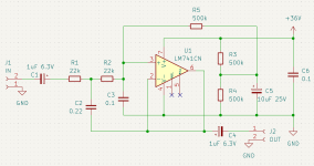

R3 and R4 can be anything within reason, the original was OK.
They only load the supply. R5 is probably OK but it is a bit large and may cause noise.
Take R5 about 5x to 10x times of R1 and R2, so its impact will be negligeable.
It will only slightly detune the filter.
I would decrease anyway R1 and R2 and increase the filter caps the same factor.
Smaller value R's means lower noise.
Jan
I don't know, I never was in favor to run away from a problem just because it seems hard at first glance ;-)Dear OP, try to use a dual supply or do an inverting filter that would leave the non-inverting pin free for biasing purposes.
Only to end up with another problem that seems hard at first glance....
Jan
Last edited:
Active filters are inherently dual supply circuits, so I'd recommend that if you need a virtual ground make one that's buffered with another opamp and provides "ground" to all the active filter stages, rather than bodge one into each active filter circuit itself.
Like this; deliberate drive your car against a wall to see if you can think up a better way to remove the dents?I don't know, I never was in favor to run away from a problem just because it seems hard at first glance ;-)
Only to end up with another problem that seems hard at first glance....
Jan
I just wanted to resolve the OP's struggle to keep the filter single supply and non-inverting at the same time ... Most circuits could be made single / dual supply at will, with some changes though.I don't know, I never was in favor to run away from a problem just because it seems hard at first glance ;-)
Only to end up with another problem that seems hard at first glance....
- Home
- Design & Build
- Electronic Design
- 1st order vs 2nd order filters and op-amps