Hi all,
Thank you for your comments.
The smps is purposely not regulated and designed to work at around f0, it is not a matter of saving some cents for opto feedback. The PFC is regulated at 390v but like every pfc regulator its transient response is slow. The purpose of this project is to replicate the behavior of a 50hz transformer plus rectifier and bulk capacitors but at a much smaller size. In a circuit like that with very high Lp the regulation will be very hard to achieve at low load. If I wanted to build a standard regulated LLC converter Lp should be in range of 100...200uH and not 2mH as it is now. This is done on purpose to see what happens keeping the frequency at f0 thus in the ideally load independent point. I have no need to be short circuit protected even though a current limit is p2resent to manage sudden load transients. The frequency will never change so that the converter can never go into capacitive mode potentially hazardous for the primary FETs.
In this circuit there should be no limit on the available power except thermal issues and saturation of the resonant choke; the OCP is set so far away from the saturation.
Dead time: In my circuit I don't think I will be able to keep ZVS at no load ( not enough reactive current to discharge Coss due to high Lp). I am hovever using FETs with fast body diode so that it has to be checked if it is a real issue. In case the transformer can be gapped to reduce Lp and increase the reactive current to reach ZVS.
Capacitor: wima FKP is in my opinion the best capacitor available for this application; they are however quite bulky. The current in each capacitor is 3.2Arms at 1kW load. I am using Panasonic ECWF 47nF 1000v which is rated 3.5A @ 100kHz. Taking into account that it is used to power an audio amp the average power will be much lower than this so I think that I am on the safe side. Wima FKP was not available otherwise it will be my tirst choice.
Light bulb: it is true it does not save you from blowing FETs if something goes wrong, the energy stored in the primary capacitor is probably 1000 times what is needed to blow it..... however it can save you a lot of troubles because you don't have a dead short on the mains with energy much greater than the one in the capacitor.
Of course, it is tested and works very nice. FB is not a such issue, that can be easily compensated with proper ERR OP.
Also, you will be surprised how easy L from that filter can be made opposite to some standard approach with separate inductor which need to be almost the same size as main transformer.
If you are interested in more readings on this matter, try with Google Translate and take an attention on ALL Macola's posts:
Nas LLC sa FSFR2100
Last edited:
@mag
I still cannot find a replay to my question, are you facing voltage skip in the LOAD / UNLOAD the PFC?
For example, load it with 100W, then see if the voltage will jump then goes back to the regulated value.
I had that problem all the time with all PFC chips, until I found the magical chip!
I still cannot find a replay to my question, are you facing voltage skip in the LOAD / UNLOAD the PFC?
For example, load it with 100W, then see if the voltage will jump then goes back to the regulated value.
I had that problem all the time with all PFC chips, until I found the magical chip!
@Cresnet
PFC is a kind of bust converter with current FB and same rules for controlling it applies as in other/standard boost or buck converters.
In other words, you probably facing problems with bad FB compensation or too slow FB response which can lead to large overshot (voltage "jump") = bad transient response.
Almost every PFC control chip will result in poor performance if you don't implement correct FB.
PFC regulation depends on loop bandwidth and the value of the bulk cap.
is true that is slow but but jumps on PFC voltage when loading/unloading are
quite limited if it is correctly designed.
On top of that FAN6961 has a kind of adaptive compensation of the error amp;
if it sees that the error is higher than a threshold it pushes more current out of the OTA to speed up the regulation (dynamically increases the loop BW).
@yu3ma: FAN6961 works in voltage mode not in current mode, current measurement is used only for protection purposes
Also, you will be surprised how easy L from that filter can be made opposite to some standard approach with separate inductor which need to be almost the same size as main transformer.
I managed to use a single primary with sufficient leakage inductance for an LLC SMPS.
Its odd but the right leakage inductance just fell out of what I wound first time.
@nigelwright7557
You probably mean on leakage inductance of main (integrated) transformer.
Talk with @mag was about one additional inductor for notch filter. That filter is not so common in standard LLC topology, at least @mag didn't know about that.
But it is interesting that those inductor for filter also can be made by using body of main transformer and proper winding method!
Last edited:
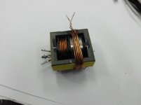
@yu3ma: is this winding outside the core used to increase the leakage inductance?
I suppose its value is quite low..... don't you have any emc related issues by winding like that due to the huge uncoupled magnetic flux?
@nigelwright: I have never used the integrated magnetic approach; with two separate parts you have more flexibility in choosing the values of lp and lr. Of course more space is needed but in my opinion the performance are better and the emc problems are reduced.
It is difficult to obtain a certain Lr with a split bobin winding , taking a lot of trial and error. for a one of design I thin a combination of internal leakage and external inductance is the best, because the lekage part is unsaturable but any external inductor will be subjected to quite large fieldsstrengths and thus needs to be sized accordingly to avoid saruration, especially at short conditons. The external inductor is thus only a fraction of total inductance and used to trim the circuit to the right resonance.
Yum3a , the external winding is your notch inductance? But it will absorb stray flux aswell?
Yum3a , the external winding is your notch inductance? But it will absorb stray flux aswell?
@mag and @rikkitikkitavi
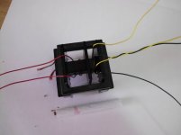
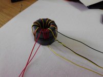
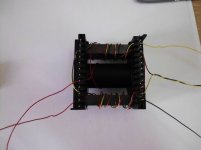
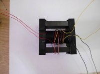
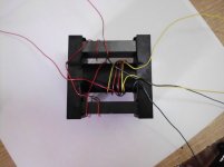
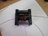
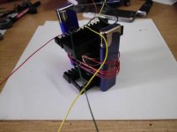
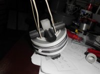
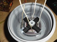
Additional windings on picture is one way of realization inductor for mentioned notch-filter. That inductor have small influence on transformer's "default" behavior as windings are over all 3 parts of transformer's core and mag flux are canceled.
It is true that side effect is large stray flux from that inductor but that is some compromise for compact design with some fine electrical feature of converter which we can have using such notch-filter.
With proper placements of components on PCB it is possible to lower down it's influence on other near by components. Anyway we need metal shield over whole converter so those stray flux will be also kipped inside the case.
--
By my opinion there is no need to use separate inductor for Llik, maybe just for educational purpose as there is one mayor disadvantage using non-integrated transformer as transformer need to have strongly coupled windings and that will rise stray capacitance (for example just 3-5pF vs >50pF for non-integrated transformer) of prim/sec and lower down it isolation/safety voltage margin.
With integrated transformer we can have very large isolation barrier quite easy.
Alos it is true that winding integrated transformer is more complex and require several tries to get required leakage and magnetizing inductance, but once you get it, it is easy to reproduce on same cores/bobbins with some acceptable tolerance.
Geometry and windings placements is very very important and it is bit hard to calculate all that, so iterative tries are maybe more easier way.
Here is one useful document, "Design guideline for magnetic integration in LLC resonant converters":
http://www.researchgate.net/profile...converters/links/0c960521f093dc8831000000.pdf
There are many different ways to get leakage inductance, here are some practical examples (Macola's photos):
Attachments
-
 hi_Ie_low_Ae.JPG70 KB · Views: 173
 -
 hi_Al_toroids.JPG127.3 KB · Views: 169
 -
 hi_Ae_low_Ie_4.JPG76.1 KB · Views: 161
 -
 hi_Ae_low_Ie_3.JPG83.9 KB · Views: 398
 -
 hi_Ae_low_Ie_2.JPG80.6 KB · Views: 414
 -
 hi_Ae_low_Ie_1.JPG84.1 KB · Views: 418
 -
 ext_L.JPG77.9 KB · Views: 431
 -
 distanca.JPG101.4 KB · Views: 425
Last edited:
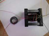
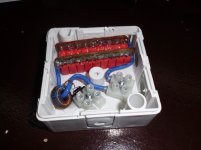
Or something like this for some high voltage application (kind of combined serial/parallel resonant converter), transformer is in box filled with petroleum for high voltage isolation …
Last photo is resonant capacitor with current transformer, just to get a picture about power of this converter")
This design/approach is already tested and work in some industrial application in very harsh environment without any problems for many years ...
Last photo is resonant capacitor with current transformer, just to get a picture about power of this converter
This design/approach is already tested and work in some industrial application in very harsh environment without any problems for many years ...
Attachments
Last edited:
@nigelwright7557
With dsPIC?
Yes, it is possible to utilize now modern MCU/DSCs for LLC SMPS.
But we always will reach some limits due processing speed …
At moment TI's C2000 DSC (Piccolo) looks promising and can get near analog controllers.
I used PIC16F506 running at 20MHz.
It used 166KHz or 125KHz for regulating the output.
On power up it used 166KHz to soft start the SMPS.
On power up it also gave the power supply caps time to charge up.
The PIC also provided the correct dead time.
#include p16f506.inc
LIST R=DEC
; LIST
;----- CONFIG Options --------------------------------------------------
;_OSC_LP EQU H'0FF8' ; LP oscillator and 18 ms DRT
;_LP_OSC EQU H'0FF8' ; LP oscillator and 18 ms DRT
;_OSC_XT EQU H'0FF9' ; XT oscillator and 18 ms DRT
;_XT_OSC EQU H'0FF9' ; XT oscillator and 18 ms DRT
;_OSC_HS EQU H'0FFA' ; HS oscillator and 18 ms DRT
;_HS_OSC EQU H'0FFA' ; HS oscillator and 18 ms DRT
;_OSC_EC EQU H'0FFB' ; EC Osc With RB4 and 1.125 ms DRT
;_EC_OSC EQU H'0FFB' ; EC Osc With RB4 and 1.125 ms DRT
;_OSC_IntRC_RB4EN EQU H'0FFC' ; INTRC With RB4 and 1.125 ms DRT
;_IntRC_OSC_RB4EN EQU H'0FFC' ; INTRC With RB4 and 1.125 ms DRT
;_OSC_IntRC_CLKOUTEN EQU H'0FFD' ; INTRC With CLKOUT and 1.125 ms DRT
;_IntRC_OSC_CLKOUTEN EQU H'0FFD' ; INTRC With CLKOUT and 1.125 ms DRT
;_OSC_ExtRC_RB4EN EQU H'0FFE' ; EXTRC With RB4 and 1.125 ms DRT
;_ExtRC_OSC_RB4EN EQU H'0FFE' ; EXTRC With RB4 and 1.125 ms DRT
;_OSC_ExtRC_CLKOUTEN EQU H'0FFF' ; EXTRC With CLKOUT and 1.125 ms DRT
;_ExtRC_OSC_CLKOUTEN EQU H'0FFF' ; EXTRC With CLKOUT and 1.125 ms DRT
;_WDT_OFF EQU H'0FF7' ; WDT disabled
;_WDT_ON EQU H'0FFF' ; WDT enabled
;_CP_ON EQU H'0FEF' ; Code protection on
;_CP_OFF EQU H'0FFF' ; Code protection off
;_MCLRE_OFF EQU H'0FDF' ; RB3/MCLR pin functions as RB3, MCLR tied internally to VDD
;_MCLRE_ON EQU H'0FFF' ; RB3/MCLR pin functions as MCLR
;_IOSCFS_OFF EQU H'0FBF' ; 4 MHz INTOSC Speed
;_IOSCFS_ON EQU H'0FFF' ; 8 MHz INTOSC Speed
;20MHZ
__CONFIG _MCLRE_OFF & _WDT_ON & _CP_OFF & _OSC_HS
;*****************************************
;SUBWF FLAGS
;IF W > MEM THEN NC
;IF W = MEM THEN C
;IF W < MEM THEN C
;IF W<= MEM THEN C
;IF MEM>=W THEN C
;IF MEM<W THEN NC
;*****************************************
#DEFINE SET0 1
#DEFINE SET1 2
#DEFINE SET2 4
#DEFINE SET3 8
#DEFINE SET4 16
#DEFINE SET5 32
#DEFINE SET6 64
#DEFINE SET7 128
#DEFINE LED PORTB,0
#DEFINE OPTOINPUT PORTB,1
#DEFINE NOTOVERCURRENT PORTB,2
;PORTC = GATES
FIRSTRAM EQU 0XD ;16F506 RAM START ADDRESS
;10H TO 1FH IN BANK 0
CBLOCK FIRSTRAM
TEMP
TEMP1
TEMP2
TEMPL
TEMPM
PULSES
ENDC
ORG 0
INCLUDE MACRO.ASM
CLRWDT
CLRF FSR ;BANK 0 RAM
MOVWF OSCCAL ;SET UP OSC FREQ ACCURATELY
MOVLW 0X30 ;A2D ALL OFF
MOVWF ADCON0
CLRF PORTC ;ALL MOSFETS OFF
MOVLW 0
TRIS PORTC
CLRF PORTB ;LED OFF
MOVLW SET1+SET2 ; OPTO AND NOTOVERCURRENT ARE INPUTS
TRIS PORTB
MOVLW 0X41 ;COMPARATORS OFF
MOVWF CM1CON0
MOVWF CM2CON0
CLRF VRCON
MOVLW 0XC0 ;DISABLE WEAK PULL UPS ON PORTB
OPTION
;WAIT 4 SECS TO LET POWER SUPPLY CAPS CHARGE UP
MOVLW 4
CALL WAITWSECONDS
;**********
;SOFT START
;**********
RESTART
MOVLW 0
MOVWF TEMPL
MOVLW 20 ;20ms
MOVWF TEMPM
SOFTSTART ;166KHz 30 cycle loop
MOVLW 1
CLRF PORTC ;DEADTIME
NOP ;DEADTIME
MOVWF PORTC
;HAVE TO IGNORE OVER CURRENT HERE as s/c to start with
CLRWDT
NOP
NOP
NOP
NOP
NOP
NOP
NOP
NOP
NOP
NOP
MOVLW 2
CLRF PORTC ;DEADTIME
NOP ;DEADTIME
MOVWF PORTC
;;;;;;;;
NOP
NOP
NOP
NOP
NOP
NOP
NOP
NOP
DECFSZ TEMPL,F
GOTO SOFTSTART
DECFSZ TEMPM,F
GOTO SOFTSTART
;*************************************************
;based on 30uh leakage inductance Lr, Lm =155uH and 200nf Cr
;*************************************************
ON BSF LED ;POWERED UP OK
MLOOP
BTFSC OPTOINPUT
GOTO SLOWCLOCK ;GO IF OPTO HIGH (VOLTS TOO LOW)
;;;;;;;;;;;;;;;;;;;;;;;;;;
;FASTCLOCK
; 166KHZ 2 * 15 CYCLE LOOP
FASTCLOCK
CLRF PORTC ;DEADTIME
MOVLW 1 ;DEADTIME
MOVWF PORTC
;;;;;;;;;;;;
CLRWDT ;LET SETTLE 800ns
NOP
NOP
NOP
BTFSS NOTOVERCURRENT ;GO IF OVER CURRENT
GOTO BROKEN
BTFSS NOTOVERCURRENT ;GO IF OVER CURRENT
GOTO BROKEN
BTFSS NOTOVERCURRENT ;GO IF OVER CURRENT
GOTO BROKEN
BTFSS NOTOVERCURRENT ;GO IF OVER CURRENT
GOTO BROKEN
CLRF PORTC ;DEADTIME
MOVLW 2 ;DEADTIME
MOVWF PORTC
;;;;;;;;;;;;
NOP
NOP
NOP
NOP
NOP
NOP
NOP
NOP
GOTO MLOOP
;*************************
;125KHZ 2* 20 CYCLE LOOP
SLOWCLOCK
CLRF PORTC ;DEADTIME
MOVLW 1 ;DEADTIME
MOVWF PORTC
;;;;;;;;;;;;
CLRWDT ;LET SETTLE 800nS
NOP
NOP
NOP
BTFSS NOTOVERCURRENT ;GO IF OVER CURRENT
GOTO BROKEN
BTFSS NOTOVERCURRENT ;GO IF OVER CURRENT
GOTO BROKEN
BTFSS NOTOVERCURRENT ;GO IF OVER CURRENT
GOTO BROKEN
BTFSS NOTOVERCURRENT ;GO IF OVER CURRENT
GOTO BROKEN
BTFSS NOTOVERCURRENT ;GO IF OVER CURRENT
GOTO BROKEN
BTFSS NOTOVERCURRENT ;GO IF OVER CURRENT
GOTO BROKEN
NOP
CLRF PORTC ;DEADTIME
MOVLW 2 ;DEADTIME
MOVWF PORTC
;;;;;;;;;;;;
NOP
NOP
NOP
NOP
NOP
NOP
NOP
NOP
NOP
NOP
NOP
NOP
GOTO MLOOP
;************************
;SLOW FLASH LED
BROKEN CLRF PORTC ;MOSFETS OFF
BSF LED
CALL WAIT250MS
CALL WAIT250MS
CALL WAIT250MS
CALL WAIT250MS
BCF LED
CALL WAIT250MS
CALL WAIT250MS
CALL WAIT250MS
CALL WAIT250MS
GOTO BROKEN
;******************************************
;FAST FLASH LED
BROKENSOFT CLRF PORTC ;MOSFETS OFF
BSF LED
CALL WAIT250MS
BCF LED
CALL WAIT250MS
GOTO BROKENSOFT
;******************************************
;63 max input
WAITWSECONDS MOVWF TEMP2
CLRC
RLF TEMP2,F ;*2
RLF TEMP2,W ;*4
GOTO SECS
WAIT1SECOND
MOVLW 4
SECS MOVWF TEMP2
L3
MOVLW 250 ;250MS LOOP
MOVWF TEMP1
L2
MOVLW 250 ;1 MS LOOP
MOVWF TEMP
L1 CLRWDT ;10 CYCLE LOOP
NOP
NOP
NOP
NOP
NOP
NOP
NOP
NOP
NOP
NOP
NOP
NOP
NOP
NOP
NOP
NOP
DECFSZ TEMP,F
GOTO L1
DECFSZ TEMP1,F
GOTO L2
DECFSZ TEMP2,F
GOTO L3
RETLW 0
;************************************
WAIT1MS MOVLW 250
MOVWF TEMP
W1M CLRWDT ;20 CYCLE LOOP
NOP
NOP
NOP
NOP
NOP
NOP
NOP
NOP
NOP
NOP
NOP
NOP
NOP
NOP
NOP
NOP
DECFSZ TEMP,F
GOTO W1M
RETLW 0
;***********************************
WAIT250MS MOVLW 250
MOVWF TEMP2
W2M CALL WAIT1MS
DECFSZ TEMP2,F
GOTO W2M
RETLW 0
;*************************************
WAIT50MS MOVLW 50
MOVWF TEMP2
W2M50 CALL WAIT1MS
DECFSZ TEMP2,F
GOTO W2M50
RETLW 0
;*************************************
Great, with 8bit PIC! I like that
But for some "serious" performance consider for example dsPIC33EP128MC502. We need to be able to run PID control which require a lot of calculating power (required floating point HW).
They have more advanced and very fast internal PWM module with dedicated sub-modules for fine control of driving stage and protection independent of MCU's core.
Here is one simple schematic utilizing dsPIC in full bridge configuration to get an Audio Class-D amplifier.
Just an example how fast that dsPIC can work … And that amplifier sounds not so bad … not Hi-Fi …
Attachments
Last edited:
- Status
- This old topic is closed. If you want to reopen this topic, contact a moderator using the "Report Post" button.
- Home
- Amplifiers
- Power Supplies
- 1kW resonant SMPS