I have been looking at doing a phono stage for quite a while now and having just "retired" I think I may get to start actually playing with it. I had been looking at passive v.s. active v.s. hybrid and was tending toward the later but I have become enamored of the idea of doing a battery powered version using either cordless tool or E-bike batteries. E-bike batteries are reasonably priced in the 36V models but horrendously expensive in the 60V models but tool batteries in 60V seem pretty affordable.
So in that vein I think that passive would be better for battery power as the supply voltage would have less effect on the response than it would using FB EQ. So I came up with this using a two stage FB amplifier front end followed by a single output stage with passive eq in between. Response follows the calculated values pretty closely but there is a 1dB per octave roll off starting at 200Hz. Being less than even a first order roll off I assume that it must be an artifact of the inverse RIAA model I picked up here rather than an actual behavior of the circuit. Can anyone confirm or destroy my reasoning here?
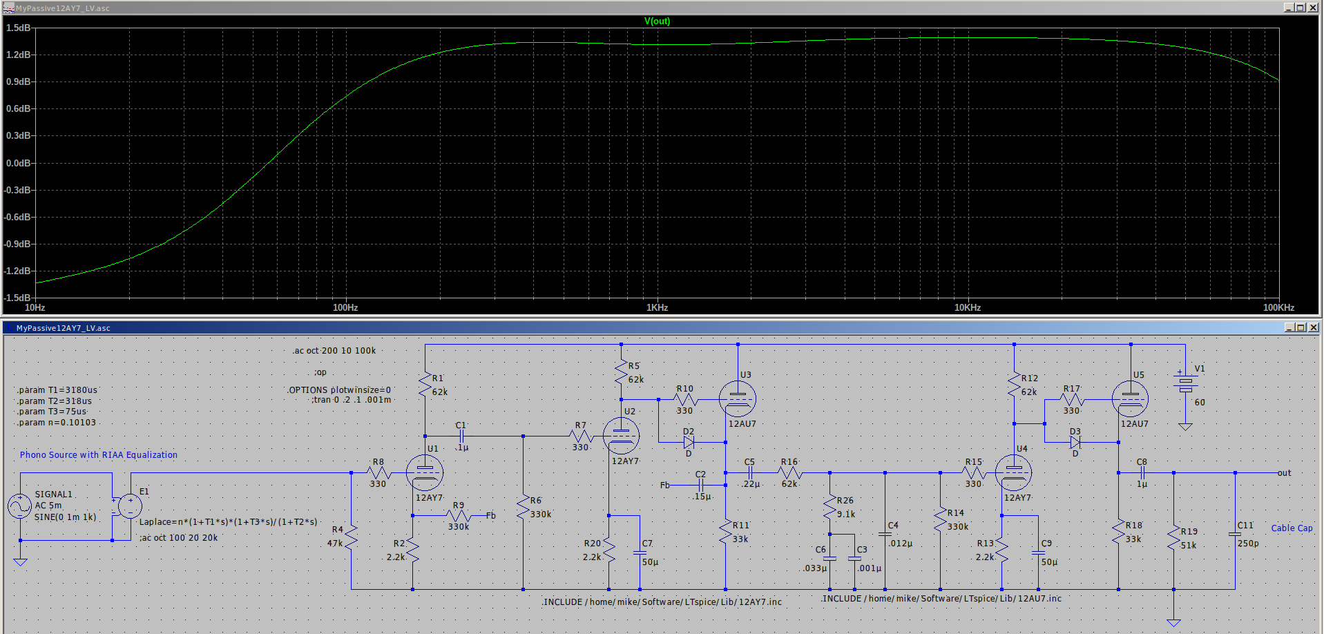
So in that vein I think that passive would be better for battery power as the supply voltage would have less effect on the response than it would using FB EQ. So I came up with this using a two stage FB amplifier front end followed by a single output stage with passive eq in between. Response follows the calculated values pretty closely but there is a 1dB per octave roll off starting at 200Hz. Being less than even a first order roll off I assume that it must be an artifact of the inverse RIAA model I picked up here rather than an actual behavior of the circuit. Can anyone confirm or destroy my reasoning here?
Attachments
Possibly an interaction between the RIAA curve and the 3.2Hz pole due to R9/C2 and the 1.8Hz pole due to C5/(R16+R14)
Cheers
Ian
Cheers
Ian
Any slope is possible between a pole and zero, a high-cut and a low-cut.
The location here suggests your gain below 50Hz is not proportional to your gain at 500Hz-2kHz. That's a common failing of simpler passive RIAA boxes. With 3 stages it is not usually a problem, but I'm not about to do the math.
Here is an iRIAA which I am pretty confident about. The Laplace version looks same-as yours? (The swap of T1 and T2 should commute.) Alternatively there is Koren's plain-parts plan, which goes off-track at extreme high frequency, but is very close in the real audio band.
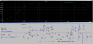
Note that you need to adjust the value of R16 to compensate for the effect of the shunt resistance of R14 - if the sum works out to 62K you will have the correct LF response. (The thevenin equivalent resistance of R14//R16 needs to match 62K) C5 should be significantly larger - I recommend 0.33uF to 1.0uF. Without R14 your EQ values match those in my RIAA calculator. Look out for other LF poles in the amplifier RC coupling. I use this exact EQ network configuration in all of my designs, and have been doing so for about 33 years now - works exactly as predicted in sims and math.
Last edited:
Thank you all three of you for your valuable input. Accounting for the parallel combination of R14 and R16 fixed the problem nicely. Output is now within +/- 0.5dB down to 30Hz. I also made a few more changes. I got rid of the first CF as it was not really necessary and added another 12AY7 to the last gain stage to make it a plate to cathode feedback amplifier similar to the first. The idea is to minimize the added distortion in the final gain stage and to allow the total gain to be set precisely where I want it to be. In the final build the FB resistor can be selected to match other line sources.
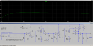
In the final stage I used separate caps for output and feedback which allowed me to get rid of a 4dB bump at 2.5Hz.
In the final stage I used separate caps for output and feedback which allowed me to get rid of a 4dB bump at 2.5Hz.
Attachments
It occurred to me last night that the caps in the FB loop are unnecessary given that the plate voltage is only about 30V and the feedback resistors are fairly large. I know that the spice models can be iffy at low voltages so the next step is to set up a test jig to come up with accurate bias.