Hans, I will add an additional part of the circuit tonight. It's a shut down circuit and it ties on to the emitters of Q9 and Q10. I think it's setup for this clipping protection. I'll post it for you thoughts.
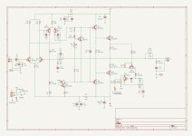
Good simu & a clear peaking just over 100kHz... how does the open loop gain behave?First image shows the FR with only Q1 and Q2 changed into MPSA14's.
These are more changes & C5 fb cap increased from 22 to 150pF.... is that not somewhat drastic?Second image shows R6 and R7 changed to 2K2 to get a 4mA VAS current.
Tweaking some cap values in the open loop analysis can yield better results to preserve performance.
The better the OL gain, thje better the CL gain!
And getting the phase rollof in the lower band more flat; the ear is susceptable to phase shifts there as is well known.
What simulation sw do you use?
Hans, I will add an additional part of the circuit tonight. It's a shut down circuit and it ties on to the emitters of Q9 and Q10. I think it's setup for this clipping protection. I'll post it for you thoughts.
Attachments
After changing these, here are the results;Yes. If the equipment that drives the input can handle a 12 kohm load, which it probably can, reducing R1 to 12 kohm would be the simplest solution. Also change C1 to 10 uF if you want to keep the low-frequency/subsonic response of the amplifier as is.
Bias, with two 0.15 emitter resistors and I'm guessing about 25mA. I set it measuring across both emitters resistors to 7mV and let it sit for about an hour. Very stable.
DC Offset: Rt= 2.7mV Lt= 1.0mV
I'll listen to it this weekend.
Can't believe you guys helped resolve this... It's bugged me for years.
Scott

This circuit is activated when > 0.6V/0.15R = 4Amp is flowing.
But there must be a resistor missing from the base of Q12 to gnd and the +15 Volt should be +32 Volt.
It is a current protection circuit for the positive halve, but not a clipping protection.
Are you sure Q12 is connected to gnd and not to -32 Volt ?
In that case it would protect both positive and negative overcurrent.
Hans
Last edited:
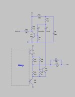
Because I didn't fully get the correct idea, I have redrawn the circuit to have a better view on it.
Q11 starts conducting at ca 1.8V/0.15R = 12Amp and not the 4Amp mentioned earlier.
When this point is reached, Diode D3 tries to pull the voltage on the lower side of R2 down to whatever the voltage on Q11's collector is at that moment, because Q11 is moving up and down with the output voltage.
When Q11's collector voltage is above the voltage on the upper side of D4, nothing happens.
However when the voltage on Q11's collector is negative, it will via D4 shut of Q12, causing the Switch_off signal to go high.
But when Q11's collector is very negative, D2 will start conducting as a diode in the opposite direction and make Q12's base also very negative, a situation that is not favourable.
So all in all, apart from a most likely missing resistor from the Q12's base to gnd, this circuit seems to have omissions or errors,
I would expect the +15V to be +32V instead to cover also overcurrent protection of the positive cycles, and a diode in series with the zener D2 to prevent Q12's base to become negative.
Hans
Attachments
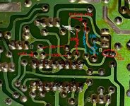
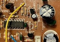
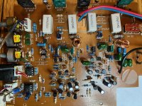
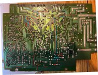
Hans, Thanks for looking at this. I will take pics of that area of the board and verify I did not goof again!
Scott
Scott
I’m using LTSpice.Good simu & a clear peaking just over 100kHz... how does the open loop gain behave?
These are more changes & C5 fb cap increased from 22 to 150pF.... is that not somewhat drastic?
Tweaking some cap values in the open loop analysis can yield better results to preserve performance.
The better the OL gain, thje better the CL gain!
And getting the phase rollof in the lower band more flat; the ear is susceptable to phase shifts there as is well known.
What simulation sw do you use?
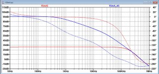
I just tried to get the thing stable and didn’t look at the open loop or loop gain because it was just a simple experiment, but here you are.
Hans
Attachments
Thanks Hans.
There are two zero's visible: at ~500Hz (open loop gain) and 50kHz (C7/8 or C9?).
I was mostly curious about the open loop with only Q1/2 replaced but without changing R6/7 & C5 - the peaking and the 180° phase shift in the 100-200kHz region.
There are two zero's visible: at ~500Hz (open loop gain) and 50kHz (C7/8 or C9?).
I was mostly curious about the open loop with only Q1/2 replaced but without changing R6/7 & C5 - the peaking and the 180° phase shift in the 100-200kHz region.
There is a line missing in the drawing of #55 and #63 between the base of Q5 and the anode of D1.I'll post it for you thoughts.
Not in #1 and #42.
60-Series (no turbo) from '88 ('beige') but with roo-bar, while at Lucky Bay WA in summer 2011.the toy Hj60
Broke down between Denham and Hamelin Pool Station (sold there).
Long story, tragedy, revelations, pivotal 3 month journey.
Admins & others: on my avatar. Back on topic now!
Didn't goof... on the protect portion. Amp sounds good, for an old amp. I don't have any Idea what the bias should be. At 25mA now, should it or can it go up to say 30-40?Hans, Thanks for looking at this. I will take pics of that area of the board and verify I did not goof again!
Scott
Attachments
Here’s an experiment.
Just listen to music with 25, 30 and 40mA bias.
When you don’t hear any difference, go back to 25 mA or else take the one you like most.
Hans
Just listen to music with 25, 30 and 40mA bias.
When you don’t hear any difference, go back to 25 mA or else take the one you like most.
Hans
Judging by R16&R17 = 0.15ohm, optimum bias current should be relatively high.
26mV/0.15ohm ~ 170mA.
It could be too hot. So try to find balace.
26mV/0.15ohm ~ 170mA.
It could be too hot. So try to find balace.
Thanks all for finding and fixing mistakes on this amp. I learned a lot about that part of the circuit, (LTP).
Scott
Scott
I did some listening test's @.025, .035, .043mA and at .043 (.013mV), it sounds fantastic and gets barely warm. Can't believe how good it sounds for a inexpensive amp. I did add 0.1u and 10u bypass caps on the op-amps and replaced the mylar/ ceramics with MKT's on the tone controls. It's absolutely wonderful to listen to.
Thanks sooo much for all your knowledge on these circuits.
Scott
Thanks sooo much for all your knowledge on these circuits.
Scott
- Home
- Amplifiers
- Solid State
- 1988 Amp with 0.150 vDC offset (150mV)