I would try to connect the TR5.6 collectors separately to the (+) point, and the rest of the circuit to the Vcc.
TR5/6?
Q3/Q4 (5551) and VT7/VT8 (5200) collectors are connected to + and rest is connected to VCC. ( all in the pcb).
Let me know, Thanks!
Q3/Q4 (5551) and VT7/VT8 (5200) collectors are connected to + and rest is connected to VCC. ( all in the pcb).
Let me know, Thanks!
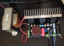
I just built one channel of this as a time pass, and it turned out to be very nice as it is. Right now my test setup is running on a low voltage surplus transformer resulting in only 16V rectified, and 13.8V after the "regulator" (or capacitance multiplier?).
With idle current of about 1A, the temporary heat sink temperature in free air is about 150F (65c). Heat sink size: 5" x 1.375" (base+fin height) x 2.5". Measured voltage amplification is around 20.
With idle current of about 1A, the temporary heat sink temperature in free air is about 150F (65c). Heat sink size: 5" x 1.375" (base+fin height) x 2.5". Measured voltage amplification is around 20.