Hi there guys, first time post here.
I bough a pair of 1969 JLH amp off ebay
Hood 1969 Class A LT1083+5200 Power Amplifier Board With 1083 Regulated Amp Boar 6162116141504 | eBay
Unfortunately they have some very poor instructions. they say to set the Idle current to 1A and set the voltage test point to 1/2 VCC.
I have tried to set the 1/2 voltage to say 20 vdc ( 28VAC input x 1.414 = 40VDC /2 = 20vdc)
Unfortunately the lowest I can get is around 22VDC and after this the Idle current start to climb dramatically ~ 5-7A
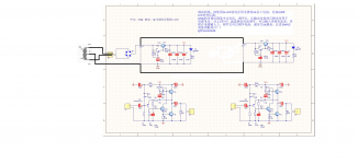
I have attached the schematic that seems very close to the actual item
Anyone with experience with this unit or similar?
Thanks!
I bough a pair of 1969 JLH amp off ebay
Hood 1969 Class A LT1083+5200 Power Amplifier Board With 1083 Regulated Amp Boar 6162116141504 | eBay
Unfortunately they have some very poor instructions. they say to set the Idle current to 1A and set the voltage test point to 1/2 VCC.
I have tried to set the 1/2 voltage to say 20 vdc ( 28VAC input x 1.414 = 40VDC /2 = 20vdc)
Unfortunately the lowest I can get is around 22VDC and after this the Idle current start to climb dramatically ~ 5-7A
I have attached the schematic that seems very close to the actual item
Anyone with experience with this unit or similar?
Thanks!

The original JLH is sensitive to transistors used. What type of device are the output transistors in your amp ?
R16 in your diagram is shown as 200k. In the original amp it was around a 500 ohm part. This resistor value is critical and if it is to low then the current will be to high. Try measuring the value of the preset and see what resistance you have.
If there is doubt then try fitting a 2k2 (2200 ohm) resistor in place of the preset and then test the amp. It should work OK at low levels and the current should be very low.
The original JLH is sensitive to transistors used. What type of device are the output transistors in your amp ?
R16 in your diagram is shown as 200k. In the original amp it was around a 500 ohm part. This resistor value is critical and if it is to low then the current will be to high. Try measuring the value of the preset and see what resistance you have.
If there is doubt then try fitting a 2k2 (2200 ohm) resistor in place of the preset and then test the amp. It should work OK at low levels and the current should be very low.
Hi there Mooly,
The Output Transistors are Toshiba 2SC5200 (Fake or real is unknown but look Ok quality.)
Turns out I had messed up that markings of the VX ( 1/2 voltage adjustment pot R14/R16) and Idle A Pot (R13/R15) and now with those corrected I am able to get 20 VDC and 1A current.
I presume the 1/2 voltage adjustment is to set the voltage split to make the 2 sides of the output waveform but what effect does the idle current have ( is more better?)
Thanks Simba
And simba185 you'll get more JLH gurus at the very large "JLH 10 watt class-A" thread elsewhere on this site.
Also Geoff Moss's "Class-A amp" site, now hosted by Elliott Sound Products in Sydney, is "The Bible" for this particular amp'
Well worth a look...cheers Jonathan
Also Geoff Moss's "Class-A amp" site, now hosted by Elliott Sound Products in Sydney, is "The Bible" for this particular amp'
Well worth a look...cheers Jonathan
Doubt they are real 2SC5200 when the rest of the parts are TIP41 and 2N5401. Almost certainly they are fakes which are really TIP3055. The 3055 should be adequate anyway.
Hi there Mooly,
The Output Transistors are Toshiba 2SC5200 (Fake or real is unknown but look Ok quality.)
Turns out I had messed up that markings of the VX ( 1/2 voltage adjustment pot R14/R16) and Idle A Pot (R13/R15) and now with those corrected I am able to get 20 VDC and 1A current.
I presume the 1/2 voltage adjustment is to set the voltage split to make the 2 sides of the output waveform but what effect does the idle current have ( is more better?)
Thanks Simba
Pleased to hear its working OK. The 20 volt setting does indeed allow the amp output to swing equally, both toward the positive and rail and ground. It should be set to equal one half the supply voltage.
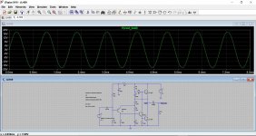
The bias current directly relates to the maximum available current output the amp can deliver (because of the amps Class A design). Running on 40 volts means you need a current of around 1.3 amps to allow the amp to deliver maximum output into 8 ohms.
This shows a bias current of 1.3 amps and 0.5 amps. Notice the output voltage on the left hand scale. Last picture shows maximum undistorted output available at 0.5A bias. The lower the bias current, the cooler the amp runs.
Attachments


Thanks Guys!
Mooly- Power vs temperature- got it!
Jaycee - is there a point to upgrade some of the components on this board or is it better putting $ into quality power supply and interconnection components?
Thanks, Simba
Mooly- Power vs temperature- got it!
Jaycee - is there a point to upgrade some of the components on this board or is it better putting $ into quality power supply and interconnection components?
Thanks, Simba
I would suggest that - if you deliberatelly under-bias the JLH amp - drop the V/2 setting for a Volt or two (from 20V to 18-19V).
Why? This would allow for a bit more symmetry in amp's output clipping points.
Why? You can gain a Volt or so of usable music output this way. "More" equals "more".
Why? This would allow for a bit more symmetry in amp's output clipping points.
Why? You can gain a Volt or so of usable music output this way. "More" equals "more".
So finally getting back to this project.
I have a very nice 22-0-22 toriod transformer, can this be used?
Or is a 22-0 , 22-0 dual output transformer required?
Thanks.
I have a very nice 22-0-22 toriod transformer, can this be used?
Or is a 22-0 , 22-0 dual output transformer required?
Thanks.
I kind figured as such,
So according the schematics in previous posts I should just jump the 0v line to both pin 2 on p5 and p6.
Thanks.
So according the schematics in previous posts I should just jump the 0v line to both pin 2 on p5 and p6.
Thanks.
Last edited:
An externally hosted image should be here but it was not working when we last tested it.
#10 dual output transformer required? -Yes!
Last edited:
If it is possible to split the windings at the "0" point, use separate windings. If not, change the rectifier circuit.
Connect "0" to ground (common for two channels). Add VD1 and VD2. Connect output "ID" to "2" (both channels).
Connect "0" to ground (common for two channels). Add VD1 and VD2. Connect output "ID" to "2" (both channels).
Humm I don't think it can be easily split ( I don't want to wreck it)
You lost me at "Add VD1 and VD2. Connect output "ID" to "2" (both channels)"
Thanks for the help!
You lost me at "Add VD1 and VD2. Connect output "ID" to "2" (both channels)"
Thanks for the help!
In my view, your 2x22 VAC transformer would be "perfect" for the task in a centre-tap full wave rectifier configuration (using two diodes). However, the idea of regulated power supply makes me feel sick.
If it is possible to split the windings at the "0" point, use separate windings. If not, change the rectifier circuit.
Connect "0" to ground (common for two channels). Add VD1 and VD2. Connect output "ID" to "2" (both channels).
3.3. Однофазный двухполупериодный выпрямитель
????????????????? ??????????? ?? ??????? ??????. ????????? ?????? ?????? ?? ???????? ???? ???????? ????????
Last edited:
Ahh gottcha! Just wasn't sure what were were talking about lol -Center tap Rectifier.
OK so I can try and bypass or remove the original bridge rectifier and build my own center tap rectifier to feed DC to both L and R channels. I wonder if its worth using schottky diodes to try and reduce the voltage drop and heat loss.
Another idea is if its worth it to try and remove the "Regulated" power supply completely and use my own to feed VCC directly. (this is a bit more work I think)
Thanks!
It's easy to get around. Wire (0) to ground. Two diodes for a large power supply capacitor (+ C3). On the other channel, turn on two diodes on (+ C4).
(this is a bit more work I think) - more capacitors🙂
(this is a bit more work I think) - more capacitors🙂
Last edited:
- Home
- Amplifiers
- Solid State
- 1969 JLH "Regulated" DIY AMP