Hey guys, ive been a member for a while but inly posted once regarding a organ amp, and though i havent had much time to post in here latley my confidence has grown a bit and I have done quite a few capacitor changes, power cord changes and small mods on guitar ands and converted a few tube pa amps to be more guitar friendly. This one had me scratching my head...
I bought this bandmaster from a friend from high school whi just bought a house with it and a nonmatching cab in the basement. He is not a musician and had no interest in it so he sold it to me (after pugging it in without the load of a cab and no input, blowing a fuse and getting shocked) as is for 375$ with the cab.
Now for the confusing part, i did the standard procedure electrolytic capacitors, omitted the ground switch and two conductor cord, and a the resistors on the power tube sockets as they looked slightly burnt, even though they were within spec. I tried it, and got no output whatsoever.
At this point i checked voltages, which seemed fine, and moved on to checking resistance to ground and between windings on the output transformer, and everything seemed fine. The amp already had a replacement OT from a bassman of the era, (as well as a NFB loop mod with a hole drilled in back for a pot 😡)so i decided what the hell its not an original OT and everything pointed to it so i bought a classictone OT (pn: 40-18008) with 4 and 8 ohm secondarys with the intention of using the existing ground switch as an impedence switch.
Got it installed, and realized my ground switch only works on one position. Nbd, ill order a new and for now leave it at 4 ohm output. went to check voltages without tubes installed and popped a fuse. I was under the impression you should be able to check voltages wothout tubes installed, is that not the case for a SS rectifier? So anyway i thought maybe that was the case(apparently not lol), and decided to install tubes to check voltages. I had a load i though was a 4 ohm cab attached to it (turned out to be 8) and guitar plugged it noodling until it warmed up and when it did tone was Inredible. Played for litterally 15 seconds, reached to put the guitar down and grab my meter and sudden the insulation on the brown wire of fhe new OT caught fire.1st 6l6 tube socket, pin #3. I hit the switch in seconds flat and once i drained the capacitors ,measured the OT resistances and choke everything seems fine, and the wire is just slightly charred where it caught fire momentarily.
Im starting to supect the diodes? Could the mismatched impedenace cause this? Or is my PT junk maybe? Do you think the previous owner cause damage to it or was this the reason it was abandoned in the first place? One more thing.. Brand new ussr 6l6 equivalents the long life e model and the weren't biased yet. I dont know what to think with this one and honest am i little worried to turn it back on to check voltages at this point. any input would be greatly appreciated.
Thanks
Attachments
Last edited:
You are right in the assumption that the amp should not blow fuses with no tubes in sockets. Check for shorted rectifiers and caps, and for bad wiring or touching terminals, or other bodging, before applying power again. Once the power supply operates without danger of popping fuses, I would definitely rig a current limiter to the mains supply before applying line power.
With any equipment received in non-working condition, I always assume everything that can be wrong, is wrong. I routinely verify correct wiring and resolder connections to eliminate doubt before moving onto resistance and continuity measurements. Please don't get shocked or start any more fires before you figure out the underlying fault.
With any equipment received in non-working condition, I always assume everything that can be wrong, is wrong. I routinely verify correct wiring and resolder connections to eliminate doubt before moving onto resistance and continuity measurements. Please don't get shocked or start any more fires before you figure out the underlying fault.
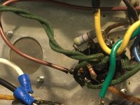
I suspect it arced to the heater wire next to it. Are they as close as they appear? Any darkness on the green cloth? This could happen with or w/o tubes installed in that amp.
You are right in the assumption that the amp should not blow fuses with no tubes in sockets. Check for shorted rectifiers and caps, and for bad wiring or touching terminals, or other bodging, before applying power again. Once the power supply operates without danger of popping fuses, I would definitely rig a current limiter to the mains supply before applying line power.
With any equipment received in non-working condition, I always assume everything that can be wrong, is wrong. I routinely verify correct wiring and resolder connections to eliminate doubt before moving onto resistance and continuity measurements. Please don't get shocked or start any more fires before you figure out the underlying fault.
I appreciate the concern, and agree saftey is the utmost importance working with any electricity, especially high votage! I assure you if i wasn't 100% sure if my ability i wouldnt touch it with a ten foot pole. As far as finding the underlying fault i thought i found it with the original filter caps bubbling, but i now wonder if this larger problem may have contributed to some of that issue.
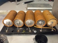
I replaced every electrolytic as well as the resistors on the filter cap board, retube as well as the new OT now. I started with a thorough check before the post(twice), but hopefully its just something simple I've overlooked... The new uf4007's are on there way from amazon as well as the socket for my limiter im going to build so i guess im dead in the water until i get that all straightend out.
Attachments
I suspect it arced to the heater wire next to it. Are they as close as they appear? Any darkness on the green cloth? This could happen with or w/o tubes installed in that amp.
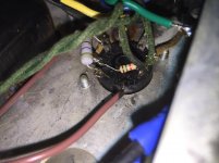
Yes you are correct that wire is blackend and from the angle does look shorted, but it wasnt making a connection, and i believe it was only slighty blackend due to the momentary wire insulation fire. It actually almost looks like it shorted to ground in the picture ive included there is a small black spot below the tube socket.
Attachments
Beware of carbon tracking on burned insulation materials including non-ceramic tube sockets. The tracking will act as a poor conductor which can lead to further problems.
Last edited:
Been there.....blown that.....
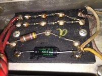
The normal voltage on that brown wire is about 900 volts when the amp is playing loud, but not clipping. Drive a Bandmaster into clipping with a fuzz pedal set on KILL, down on the 6th string where the speaker goes resonant, and you can have over 2000 volts on the brown and blue wires. The area where these wires connect to the tube sockets MUST be clean and nothing else should be near it. The green wire is the most likely place for an arc to jump to.
If the amp had been abused in the past (likely since the OPT had been replaced) the 6L6GC sockets may have carbon tracking. This is where some of the phenolic material has been burned into carbon and has become conductive. This usually happens between pin 3 and pin 2 inside the socket, or where the solder lugs are. This will blow fuses, and sometimes power and output transformers and diodes. Amps kept or used in damp places are worst case.
Often you can see smoke, burning, white or yellow glow, or fire coming from the area between pins 2 and 3 from the bottom of the chassis when the amp is powered up. Sometimes all the burnt material can be scraped away, and the socket cleaned up, but the proper cure is to replace both 6L6GC sockets.
The little black diodes in 60's Fenders are prone to failure, but once they blow, they remain dead. If your amp has B+ voltage, and doesn't blow the (correct)fuse instantly on power up, they are OK.
I think you guys are 100% correct with thw tube sockets. Ceramic replacements are in route from china so for now im dead in the water. Hopefully they arrive soon so i can test it out on my new light bulb current limiter!
Thanks for the replies i appreciate it everyone
Thanks for the replies i appreciate it everyone
Update
Sorry for not updating in a while but i have been pretty busy latley and just recently got back to it. So i reserected my project, replaced the diodes, power tube sockets and even put a new power transformer in it assuming there was a short on the secondary windings because both legs had continuity to ground(still soldered into the circut).
So upon fire up using my 100 watt bulb on my current limiter everything seemed good, 120vac from the power switch to nuetral conductor so i hit the standby switch and the bulb shined very brightly for a minute and dimmed gradually as the indicator light of the amp slowly brightened. I measured voltages with no tubes and everything seemed to be right where it should be so i powered down and installed power tubes. First thing i noticed was positive bias voltage 12vdc. This had me completley puzzeled, so I quickly measured other voltages before powering down and noticed all of the Dc voltages seemed very low, so i checked ac voltage again and it was at 80-90 volts which was confusing to me. Ive ran threw the schematic a few times now checking components and still i havent found any issues, and to top it off couldnt find and other posts online about posititve bias voltage, and likley causes for it. Any idea where to start looking guys?
So i hope im finally getting to the root of the problem, but would definitley appreciate any help to steer me in the right direction to the cause of this issue. I appreciate all the help you guys have given me in getting this far with the project and cant wait for any reply🙂
The bulb limiter is there to prevent the amp blowing fuses. If the bulb flashes but dims right down once turned on, then try without the bulb. The bulb is a useful tool, but it does lower all the voltages in your amp. Take the power tubes out. Power up the amp. Does it hold a fuse? Now measure voltages on the power tube sockets. If you are getting +12 instead of -50 volts bias, there is no reason to risk your new tubes. Find out what is wrong with those sockets empty. Also verify good B+ on both pins 3 and 4 of each socket.
so i checked ac voltage again and it was at 80-90 volts which was confusing to me
And to us: where-do-you-live?
Most members do not fill out this important piece of data.
80/90 volts is no big deal if through a lamp bulb limiter and in a 120VAC Country, but gross if in a 220/240V one.
So please show that for proper answers.
- Status
- Not open for further replies.
- Home
- Live Sound
- Instruments and Amps
- 1967 blackface bandmaster output transformer fire