I was looking for a good DIY amp project to get into tube amplifiers and found a 1954 Regency HF-150 on ebay. I figured that the bid price at the time was a good deal for the transformers alone so I placed my rock-bottom bid and actually won it. I've been scouring the internet for information about the amp but have come up empty handed. Has anyone heard of it? I've found lots of sites for amp refinishing with some really good tips but I need some specific schematics for this model. I'd appreciate some tips on where to look. Thanks in advance!
josh
josh
Attachments

http://www.sundial.net/~rogerr/magrevhf.htm Here's where you can find a reprint of an old review. A schematic might be tough to find. If you can locate information on each tube(pinouts),you might try drawing your own.This isn't easy,but it's an excellent exercise that will get you familiar with tube circuits. Don't try to draw the whole thing at one time.
Thanks!
I'm ordering that 1954 review that you mentioned ASAP; it seems like a good place to start. As for the schematics, the search will continue (sigh). I guess I don't really need them since I can just replace like for like as I go-- it's not as if there will be much left of the original when I'm done, save the sockets, transformers, and chassis. There's just something a little daunting about starting a trip without a map. I guess I'll just make the map as I go. I've been taking a crash course in tube circuit design as well; it seems as much art as science. Thanks again!
I'm ordering that 1954 review that you mentioned ASAP; it seems like a good place to start. As for the schematics, the search will continue (sigh). I guess I don't really need them since I can just replace like for like as I go-- it's not as if there will be much left of the original when I'm done, save the sockets, transformers, and chassis. There's just something a little daunting about starting a trip without a map. I guess I'll just make the map as I go. I've been taking a crash course in tube circuit design as well; it seems as much art as science. Thanks again!
I guess for $5,you can't go too wrong.Probably not much in there about the circuit.If you're going to get into it,definitely try drawing a schematic.It will be a learning experience.
There is a Sam's PhotoFact on this amp. The catalog # is 265-10. If you live in a large town the library might have this in the stacks and you can photo copy it. If not let me know and I can check the library here.
Alright- The amp finally arrived and it seems to be in good shape. The Sam's photofact is in the mail. I'm getting new can-caps from VibroWorld; they're hard to find! They're 20/20/20@450, 250@25 and I'm really not skilled enough to make my own. Being born in 1971, this is the first thing I've ever worked on without a PCB...
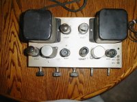
From the beginner's stuff I've read on designing tubes, I can understand most of the circuit and I'm working on my own schematic. What is the rationale for the 3 different pre-amp tubes? (see picture)
From the beginner's stuff I've read on designing tubes, I can understand most of the circuit and I'm working on my own schematic. What is the rationale for the 3 different pre-amp tubes? (see picture)
Attachments
I was looking for a good DIY amp project to get into tube amplifiers and found a 1954 Regency HF-150 on ebay.
josh
Hi Josh,
I had one of these amps when I was in high school. I don't know whatever happened to it, but I remember listening to lots of 45's and LP's on it. How is your project going ? Did you get it working yet ? PJD
Regency HF-150 ... stories
Great to see a young-timer taking an interest in these oldies. The 3 pre-amp sections are one for the phono preamp which, incidently, has several equalization modes. This amp was made right at the time when RIAA recording Equalization was standardized in 1954. Prior to that time, there were several recording eq's used AES, NARTB etc. The Wiki-pedia has some good history discussion about this.
The second tube has to do with the loudness circuit and the third 9 pin tube is a phase splitter for the push-pull output circuit. The grids for the push-pull outputs must be fed out of phase to each other and the phase splitter accomplishes this task.
BTW, where did you find this thing and how much did you have to pay for it ? I'd love to fine one myself to add to my collection. I mentioned in a previous post that I had one of these when I was in HS and college. I went to tech school for electronics from 1966-68 and at that time they were still teaching both vacuum tube theory as well as the new-fangled transistor solid state theory, as they called it.
There was a GE TV factory still in operation in nearby Syracuse where they were building hybrid tube-transistor TV's. I was fascinated by the assembly line to see how it worked. It was mostly women soldering the chassis and hooking up the PC boards to the main chassis then testing it step by step as it went down the line. This was back in the day when in America we actually made things. Those were the days.
BTW, you mentioned 1971, that was the year I got married. I still have that wife 🙂 and 6 grand children. PJD
Alright- The amp finally arrived and it seems to be in good shape. The Sam's photofact is in the mail. I'm getting new can-caps from VibroWorld; they're hard to find! They're 20/20/20@450, 250@25 and I'm really not skilled enough to make my own. Being born in 1971, this is the first thing I've ever worked on without a PCB...
From the beginner's stuff I've read on designing tubes, I can understand most of the circuit and I'm working on my own schematic. What is the rationale for the 3 different pre-amp tubes? (see picture)
Great to see a young-timer taking an interest in these oldies. The 3 pre-amp sections are one for the phono preamp which, incidently, has several equalization modes. This amp was made right at the time when RIAA recording Equalization was standardized in 1954. Prior to that time, there were several recording eq's used AES, NARTB etc. The Wiki-pedia has some good history discussion about this.
The second tube has to do with the loudness circuit and the third 9 pin tube is a phase splitter for the push-pull output circuit. The grids for the push-pull outputs must be fed out of phase to each other and the phase splitter accomplishes this task.
BTW, where did you find this thing and how much did you have to pay for it ? I'd love to fine one myself to add to my collection. I mentioned in a previous post that I had one of these when I was in HS and college. I went to tech school for electronics from 1966-68 and at that time they were still teaching both vacuum tube theory as well as the new-fangled transistor solid state theory, as they called it.
There was a GE TV factory still in operation in nearby Syracuse where they were building hybrid tube-transistor TV's. I was fascinated by the assembly line to see how it worked. It was mostly women soldering the chassis and hooking up the PC boards to the main chassis then testing it step by step as it went down the line. This was back in the day when in America we actually made things. Those were the days.
BTW, you mentioned 1971, that was the year I got married. I still have that wife 🙂 and 6 grand children. PJD
BTW, you mentioned in a previous post that you were drawing the schematic. I found a schematic in a jpg that I'll send you if you send me your email address. Also, there is a Sams Photofact available on eBay for $5 Buy it Now price. The Sam's Photofacts are thorough and invaluable for what you are doing.
eBay link: REGENCY HF-150 TUBE AMP AMPLIFIER PHOTOFACTS PHOTOFACT - eBay (item 380180214673 end time Apr-20-10 11:28:05 PDT)
PJD
eBay link: REGENCY HF-150 TUBE AMP AMPLIFIER PHOTOFACTS PHOTOFACT - eBay (item 380180214673 end time Apr-20-10 11:28:05 PDT)
PJD
- Status
- Not open for further replies.
- Home
- Amplifiers
- Tubes / Valves
- 1954 Regency HF-150 Amp???