Hello, I've just acquired a 1954 Bogen VP17X. The treble control works fine for both phono and mic. But the bass control does nothing for mic (but works fine for phono). Just wondering if something's wrong or if perhaps this is part of the design. When I got the amp it hummed and squealed when powered on; so of course I recapped, and it works nice. I also have a 1955 Bogen J330, and the tone controls work equally for both mic and phono. 
I found this schematic elsewhere in this forum but it isn't too good. But it is good enough to tell that the bass control is just before the phono input, which is one of the bottom inputs. Historically on these Bogen amps, the mic input has one more gain stage so one of the bottom inputs should be the phono. This is a good clue as to why the bass works differently for the inputs. Check the coupling cap and resistors associated with it that control. One of those is likely the problem.

Last edited:
1954 Bogen VP17X Bass Control
Thanks, boobtube. Yes, I've seen that schematic and have since purchased an original Photofact. Please view attachments. As many years as I've been looking at schematics, they still highly confuse me. Hoping you can help.
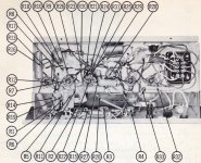
In the Photofact photo, you see R20 (20K) going from bass pot wiper, up into the circuit somewhere. In my amp, not only is R20 a 56K but it connects from bass pot wiper to the outer lug of the phono pot. Very difficult but I tried to capture that in the photos. In the schematics, there is NO R20 on the wiper of the bass pot. this is maddening.
I found this schematic elsewhere in this forum but it isn't too good. But it is good enough to tell that the bass control is just before the phono input, which is one of the bottom inputs. Historically on these Bogen amps, the mic input has one more gain stage so one of the bottom inputs should be the phono. This is a good clue as to why the bass works differently for the inputs. Check the coupling cap and resistors associated with it that control. One of those is likely the problem.View attachment 460817
Thanks, boobtube. Yes, I've seen that schematic and have since purchased an original Photofact. Please view attachments. As many years as I've been looking at schematics, they still highly confuse me. Hoping you can help.
In the Photofact photo, you see R20 (20K) going from bass pot wiper, up into the circuit somewhere. In my amp, not only is R20 a 56K but it connects from bass pot wiper to the outer lug of the phono pot. Very difficult but I tried to capture that in the photos. In the schematics, there is NO R20 on the wiper of the bass pot. this is maddening.
Attachments
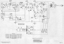

And to top it off, in the schematic R20 is a 20K grid resistor for the input section of the phase inverter tied to the top of the treble control! This is variation of a simple treble bleed control. BTW, excellent pics and it sure is nice to have a decent schematic even if it is somewhat different. These old designs are definitely different than newer ones. I think it's head scratching time for me until later. I'll try to get back to you soon.
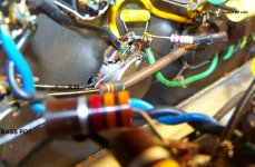
It seems that if you remove that 56K resistor and wire it up like the schematic, it should work. That .002 C12 connected between R14 and the wiper of the bass control should let it control bass for the mic input. That cap should couple the signal to the pot and it should be a bass bleed. Make sure the rest of the controls are wired up like the schematic as well. Someone has done work in the amp. That 630V yellow cap and the 220K carbon film resistor in your close-up are new.
It seems that if you remove that 56K resistor and wire it up like the schematic, it should work. That .002 C12 connected between R14 and the wiper of the bass control should let it control bass for the mic input. That cap should couple the signal to the pot and it should be a bass bleed. Make sure the rest of the controls are wired up like the schematic as well. Someone has done work in the amp. That 630V yellow cap and the 220K carbon film resistor in your close-up are new.
Oh, perhaps I failed to mention, I recapped and replaced some resistors. But the full shot of the rat's nest is exactly how it came to me. OK, so I guess I am interpreting the schematic correctly, as I do see what you see. I'm very curious to try your suggestion on removing the 56K and wiring it as per schematic, and maybe eventually using the intended 20K. Also, if I'm interpreting correctly, the resistor in question goes to 6SL7 grid pin 4. Hopefully.

Yes I did read that you re-capped; I only thought of filter caps. Yes, there should be a 20K resistor to pin 4 from the top of the treble control. As you can see they have wired it as a variable resistor instead of a voltage divider pot. Just a treble bleed control. If you don't get good results with that .002uF cap for the bass, try to temporarily twist another cap's wires around the .002 to increase the value by paralleling them. This will increase the uF value and lower the cutoff frequency. Add the values to get your final total and then use that total for your final value.
Yes I did read that you re-capped; I only thought of filter caps. Yes, there should be a 20K resistor to pin 4 from the top of the treble control. As you can see they have wired it as a variable resistor instead of a voltage divider pot. Just a treble bleed control. If you don't get good results with that .002uF cap for the bass, try to temporarily twist another cap's wires around the .002 to increase the value by paralleling them. This will increase the uF value and lower the cutoff frequency. Add the values to get your final total and then use that total for your final value.
Surely worth a try, thanks. What is meant by "treble (or bass) bleed control"? I'm fairly new to all of this.
It is usually just a cap and variable resistor or pot used together that will shunt the desired frequencies to ground and let the rest pass to the next stage. A one knob tone control is usually a treble "bleed". Also called a treble cut. Think of it as a volume control for a certain range of frequencies. Changing the value of the cap or pot changes the cut off frequency or frequency that the treble "bleed" starts at.
HI, I have not yet made any changes. I'm a little reluctant due to my uncertainly at interpreting schematics. But I realize I have to eventually, in order to determine if the unit's been modified, and to learn how the unit was intended to operate. I did mention I did jumper the bass pot over to the treble pot. The result of that was, both pots behaved as the treble pot does; that is, you can not add but can only decrease bass and treble (where "normal" is full and flat sounding). I have a feeling that may be as intended, because that's how the bass and treble controls work on my J330 from the same years. If I'm right, I'd rather leave as wired, because I like being able to add bass to records. It's a good trade off, because as I say, at "normal" everything still sounds good and full, and my main use of the unit is for playing records. (My main use of the J330 will be for microphone.)
Just FYI, almost all tone controls on guitar and PA amps are subtractive or passive. They only decrease the frequencies they were designed to control. The amp normally would operate as if all controls were maxed out. When adding volume or tone controls, that part of the circuit which it was designed to control is routed to ground and the rest of the signal passes to the next stage. When turning up the treble control what really happens is that less decrease happens, so it seems like an increase happens. Most all common Fender, Marshall and Vox tone controls work this way.
Just FYI, almost all tone controls on guitar and PA amps are subtractive or passive. They only decrease the frequencies they were designed to control. The amp normally would operate as if all controls were maxed out. When adding volume or tone controls, that part of the circuit which it was designed to control is routed to ground and the rest of the signal passes to the next stage. When turning up the treble control what really happens is that less decrease happens, so it seems like an increase happens. Most all common Fender, Marshall and Vox tone controls work this way.
THAT is very interesting and explains this mystery. I thought this maybe was just a Bogen thing. Well, then, do you suppose Bogen modified this for the VP17X so that bass can be added, because it's a record player? Seems logical. However, it doesn't seem logical that they'd do that at the expense of having the bass control do nothing for PA. Or maybe they relied on the treble control to tailor PA freqencies, as as you pointed out. Wish I had an owner's manual.
Damn, you've piqued my curiosity again. I gotta try that wiring change to the treble pot.
Last edited:
Yeah, some of these older designs leave me scratching my head too. It's probably as you were thinking, something to do with the bass control having to act differently for the phono than for voice. After all that's what the PA function is for, voice. There needs to be a wider band of frequencies adjusted for phono than for voice so the design works differently for phono than voice. When in doubt, use logic 😉
Yep. I'll probably keep it wired like that, to enjoy boosting bass for records. But I still would like to wire it according to schematics, just to learn; that is, when I'm confident I'm correctly interpreting the schematic. It is interesting, how, when I jumpered the bass control to the open lug on the treble pot (that is supposed to connect with a tube, if you'll recall), the bass pot acted exactly like the treble pot; that is, as you point out, "subtractive, passive."
That functioned exactly as it should. The resistance of the treble pot and .01uF C14 work together to determine the treble cutoff frequency and jumpering that to the bass control coupled that signal to the bass pot. Since its value is the same as the treble pot(500K), it acts just the same as the treble pot. The controls were paralleled so they perform the same function. Try increasing one and decreasing the other at the same time and then vice-versa. See if that provides any extra control.
That functioned exactly as it should. The resistance of the treble pot and .01uF C14 work together to determine the treble cutoff frequency and jumpering that to the bass control coupled that signal to the bass pot. Since its value is the same as the treble pot(500K), it acts just the same as the treble pot. The controls were paralleled so they perform the same function. Try increasing one and decreasing the other at the same time and then vice-versa. See if that provides any extra control.
Interesting, yeah, I'll try that, thanks. Did you mean to jumper them again, THEN try the simultaneous increase / decrease? Been outta commission a couple days with this son of a bitchin' sciatica.

Last edited:
Keep it wired how you like best, as you said for phono use. You said the you had control for bass that way. Might as well keep it how you like it for the way you use it most. Maybe just for experimenting you could try that jumpering it to see what happens if you feel up to it. I think we have established nothing adverse happens with either way so why not try both. That's the beauty of tube design, unless you wire up a direct short of high voltage to ground or something like that, the technology is pretty forgiving, unlike transistors which domino one failure to the next, to the next.... Once you are into the tone shaping part of the circuit, the high voltage is NORMALLY blocked by a coupling capacitor. You want to keep the high B+ voltage off the pots. Again, NORMALLY!
Interesting! https://www.youtube.com/watch?v=cOodlyOaMmI[/URL] At 2:00 he operates the controls. Again, even on his, you can hear, the controls act exactly as on mine. Either this is the factory configuration, or perhaps the dealer offered a wiring mod? Still weird though how it is wired differently from the schematic. Also, forgot to mention, I read a post somewhere where the owner is saying, same as me, in mic mode, the bass control does nothing. Boy, I wish I can find an owner's manual!
A quick thought. Those old amps were routinely changed without updates to the schematics. It's even hard to find ANY schematic at all on some. The best resource is as you have discovered, Sams Photofact site.
- Status
- Not open for further replies.
- Home
- Live Sound
- Instruments and Amps
- 1954 BOGEN Bass Control