Hi all,
Some time ago I built a 18W EL84 push pull tube amp with some parts salvaged from an old radio. The only part I didn't have on hand was the OT, make a pretty cheap amp at the end! With the help of friends we were able to acheive a pretty good result in the overall, the amp sounds pretty good, everything seems to be very stable, but I keep to think that the sound still have to be improved in a more "perfect" way, maybe it's just the tubes, or something in the schematic... I am seeking for the typical overdriven marshall sound!
Here it is
http://leadbox.servehttp.com/diyaudio/18W_nocase.JPG
http://leadbox.servehttp.com/diyaudio/18W_sche.jpg
Anybody feel free to let me know any comment or suggestion to improve that thing without too dramatically changing the concept 😀
Last edited:
I didn't knew this one, it's a kind of power scaling to reduce the B+ voltage. The amp have a master volume so I can get that cranked sound at low volume, but I wonder if a VVR produces substantially the same result? I've never used this...
I prefer to VVR just the power amp stage. The result is entirely different to having a master volume.
Part of the "Marshall" sound often comes from the tone stack being driven by a DC coupled cathode follower.
If this is more change than you wish to make to your existing project you might consider
1. Change your speaker
2. Marshall is not ashamed to use diode clipping to shape shape tone.
Happy diy.
If this is more change than you wish to make to your existing project you might consider
1. Change your speaker
2. Marshall is not ashamed to use diode clipping to shape shape tone.
Happy diy.
Part of the "Marshall" sound often comes from the tone stack being driven by a DC coupled cathode follower.
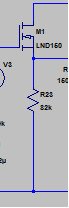
Only 2 parts required for a simple follower. See attachment.
(gate attached to plate of previous stage, source connected to a resistor and the input to your tone controls, drain to B+)
The VVR is a great suggestion too, if you want to practice with distortion, at lower volumes.
Attachments
An Apprentice says-
Although I've built several amps and studied now for about 3 or more years, tube amp principles, there's tons I don't know. That is the frame work for this question-observation.
It seems to me the associated bias and coupling caps for V1a are too small to pass anything more than mid-high frequencies. Perhaps adding a resistor in parallel with the output cap would give the sound a better harmonic mix. 10K and 270 pf in parallel or perhaps just a .1 on the output of V1a to test the theory.
Constructive criticism encouraged,
Ccat
The 2.2nF cap C2 might seem small but that's what Marshall uses in the Bright channel of some of their amps and with a 1Meg Volume control, it's not too bass restrictive. If you want more gain, bypass R5 with a 22uF cap. The value of R12 seems too high. Typical values of 820 or 470 Ohms are normal. Experiment with the value to see how it changes the tone.
That's funny because all the parts you are pointing out to me are where my friends suggested modifications. In my original diagram 47nF was used at C2, and 820 ohms for R12 at the PI. I read somewhere that with 1K2 it is a bit cold which gives a low gain and a more "frank" saturation of the PI, at the expense of the poweramp... But I wonder if R14 should also be lowered a bit. And what do you think about C7 value..?
I'll do some A/B test using different values, and will also take look at the cathode follower solution. I read a little at the Wizard, if I understand it will compress the previous stage? The mosfet you are suggested (LND150) seems pretty difficult to find by here, I will have to check out a substitute.
These are all very good advises, thank you all! If anything else seems wrong to you, feel free to let me know! 🙂
will also take look at the cathode follower solution. I read a little at the Wizard, if I understand it will compress the previous stage? The mosfet you are suggested (LND150) seems pretty difficult to find by here, I will have to check out a substitute.
)
IRF820's are often suggested for guitar amp source followers.
I'm not sure about the compression.. What I do know is, it gives you more power to drive your tone stack. And basically, some tone stacks are designed to be driven from a follower (it's usually a cathode follower using a tube, but a source follower using a mosfet does the same thing).
What I've noticed, from just randomly inserting a follower on a few different guitar amps and testing them, you'll have less loss through the tone stack (louder or distort sooner), and more high frequencies. I didn't really like the effect, when just adding one to an amp that wasn't designed to have one. The extra gain was nice, but the tonal balance was off..
What I learned is, it's best to design the tone stack with the output impedance of the previous stage in mind.
Very interresting... This amp was not originaly design to be a Marshall alike, and the mods didn't help at all, because with the values suggested by everybody here (which are close to the values I used in my original diagram) this amp is sounding very well, so I think I'm gonna go back to these values and let it go!
I'll look at some Marshall diagram more closely, I have another Transformers kit salvaged from an old EL84 push pull amp (I did not like the sound), this is my next build 🙂
- Status
- Not open for further replies.
- Home
- Live Sound
- Instruments and Amps
- 18W homemade tube amp - Need advise