So it does not have over all feedback.
Nope.
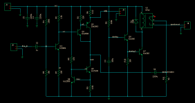
Can you explain how you determined this?the base current of Q3 is of the order of 10 to 15mA.
The bootstrapped R3 is passing about 3mA.
I would be looking at reducing R3 by a factor of 10 and maybe even lower.
I need the gain since I use some input sources with low line levels.Reduce the gain now set by 1.8k/100ohm.
By using 1.8k/330ohm you get lower distortion and a more suitable gain.
What about moving R4 to between the junction of C-E on the CFP Q2-Q3 and the output node(Q5 C)?
This way you will have some local feedback on the whole compound, getting it more linear, and achieving less distortion at the end, I suppose.
The R4 where it is now could be shorted out or set to a convenient 0.1 ohm if its sole purpose is to measure standby current.
This way you will have some local feedback on the whole compound, getting it more linear, and achieving less distortion at the end, I suppose.
The R4 where it is now could be shorted out or set to a convenient 0.1 ohm if its sole purpose is to measure standby current.
Last edited:
the base current of Q3 is of the order of 10 to 15mA.
The bootstrapped R3 is passing about 3mA.
I would be looking at reducing R3 by a factor of 10 and maybe even lower.
Instead I will ask you to look at your schematic:Can you explain how you determined this?
determine what base current flows in Q3. Clue what is a range of hFE for Q3 and what is the bias current of Q3?
determine the voltage across R3. What is the current in R3?
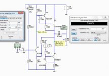
Alernative circuit with low distortion.
Here is a variant using two NPN 2SC5200 transistors.
The main difference is the FEEDBACK by resistor R9.
This makes amplifier have feedback and the distortion is much lower.
The THD 0.003% is at 1 Watt RMS output.
Max output is 4 Watt with reasonable distortion.
Regards Lineup
Here is a variant using two NPN 2SC5200 transistors.
The main difference is the FEEDBACK by resistor R9.
This makes amplifier have feedback and the distortion is much lower.
The THD 0.003% is at 1 Watt RMS output.
Max output is 4 Watt with reasonable distortion.
Regards Lineup
Attachments
- Status
- This old topic is closed. If you want to reopen this topic, contact a moderator using the "Report Post" button.
- Home
- Amplifiers
- Solid State
- 18V Class A