Hello All.
in my search for the right portable 12 to 48v converter I have found this miniature converters from Pico electronics
Although i found it expensive, i bought the PICO 12A48S.
After struggling to find a 10 uF, 78v tantalum (Kemet does it) I tested it only to find that V out is totally dependant on load.
high impedance output I guess.
The guy at Pico's actually (kindly) sent me a chart of its voltage/load relation.
It seems that it needs to be permanently at full load (26mA) to be stable at 48V... 1.25watt... and a minimum total of 130mA draw on my battery.
that's not really practical for my purpose...
i tried different ways to regulate it: TL783, 2x 24v zener diodes, and even a combination of the 783 set as current regulator and the zener diodes.
No success as the tl783 requires a Vin-Vout differential of around 20V, and somehow the load of the regulating circuit brings the Vout of the Pico's much lower than 68v.
Zener diodes have fluctuating voltage and current outputs (is that a problem for the mikes?)
None of these were satisfying as the voltage differs from at the 3 required loads:
At best set up i have 48v at no load, 47v at 10k (one mike), 46.5v at 5k (2mikes).
In this case, the max total current consumption is 72mA, wich is not bad.
So I have 2 questions:
-will that matters for the mikes safe and sound ? (if one is plugged and get 47v, then it has to stand a voltage drop to 46.5 v when 2d mike is plugged...)
-anyone can suggest a way to regulate properly (keeping total consumption of the circuit low) ? (I haven't tried transistors, don't know how to yet)
Thanks,
Fred
ps: I haven't listen to the result when actually used in a preamp so I don't know yet if its noise will be a problem....
Last edited:
push pull converter
Hi peoples
im designing a dc to dc converter with a dual polarity (+-30v) (+-6A) output.
i am using an example from Switchmode Power Supply For Car Audio
i just have trouble understanding one thing. please bear with me as i try and explain myself.
The transformer i will wind myself needs two primary and two secondary coils.
i will be applying 12v, 30A(car battery) to center tap of primary and need to get 30v and 6 amps. one for the positive rail and one for the negative rail.
I understand how to get the voltage and current on primary side of transformer. I also understand voltage on secondary of transformer. the only thing im not sure about is how on earth u can get 6A per rail when Faradays transformer equation clearly states:
v1/v2 = i2/i1
so..12A/30V = xV/30A
solving for x i get 12A on secondary.
now 12A cant be spilt to get 6A because i have two secondaries or does it??
then if so does the 30v output split so i get 15v on each rail?????????????
THanks for allowing me to confuse u
any help would be much appreciated
re:
Hey Eva thanks for your reply. so if you say the 12A is shared between two secondaries two give 6A on seperate rails, wouldnt the 30V also be shared between the two secondaries??
you probably answered me correctly i just need more of an explanation to help me understand it if you dont mind.
thanks again
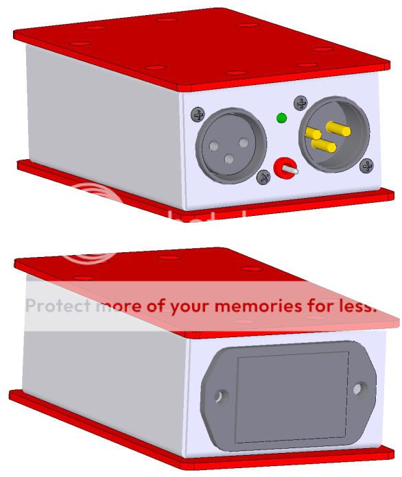
do you have a schematic, how did you wire it to the xlr's. Did you made the enclosure at your own.Untitled Document
With standard condenser microphone (current about 3mA) 9V lithum battery works about 8 hours.
My portable phantom 48V supply:
- Status
- This old topic is closed. If you want to reopen this topic, contact a moderator using the "Report Post" button.