Looking for some input to complete the design and parts gathering for a 18" 3-way speaker for home hifi using pro drivers. All will be actively divided, time aligned, and room corrected using Audiolense with a Lynx Hilo interface. Room is 27' wide, 18' deep with 22' ceilings. The back wall of the room is open to an 18' wide x 14' deep room with 10' ceilings. Seating position will be about 12" from the front of the baffles. I just received the B&C 18TBW100-4's I'm going to run sealed in about 3.75 ft3 for duty from the 30's up to around 200hz. These will be powered by a Crown XLS 1502 or 2002. The speakers will be a single stack on each side of my video screen in the family room. No separate subs.
From there, I have 3 directions I could go based on drivers I've accumulated over the years.
1. Open Baffle 12" or 15" coax - mounted in the baffle extending above the sealed bass enclosure. I have a pair of new P Audio BM-15CXA's which use the throat of the pole for the horn, and a new pair of the P Audio BM-12CXHB's which have the 40 x 90 horn mounted to the center of the driver.
2. Same 12' or 15" coax from above, but sealed.
3. Sealed 12" midbass with 1" compression driver - in a separate enclosure on top of the bass enclosure. I already have a pair of PI speakers horns used on the 3 Pi and 4 Pi Speakers and a pair of B&C DE250 drivers. I'm also considering the Radian 475pb compression driver. Been looking at the Beyma 12p80fe/v2 or the Ciare 12NDH-3 or 4 for midbass to be crossed to horn at 1000-1200 hz. I'd be willing to listen to other ideas on the 12" midbass. Most of the stuff I found online was good info back whe it was posted, but technology has eveolved.
I'm thinking, at my listening distance, the 12" coax with the 40 degree vertical horn would be better than what I think is a 60 degree conical dispersion of the 15" coax
I'm not sure if the open baffle top will work well with the sealed 18's. Would I be better off using the 12" coax sealed ?
Of course, the 18" driver will be in the lower enclosure, or on the lower part of the baffle. How far should the 12" driver be above the 18?
Thanks in advance for any input!!!
Hi! nice opening post, lots of info about the context 🙂
You could simulate if a coax in open baffle limits your top SPL. Have you zoned in what kind of SPL capability you'd like to have? If it does, then closed box it is.
Another thing, which is very different with the two, is how far the speakers are from the front wall. In general, both open baffle or closed box would have different interference with the front wall and side wall early reflections, and also vertical. In addition to sound the positioning is related to aesthetics and practical stuff that you need to work out. If these simple tests do not give you better choice yet, then you'd be better trying both by listening which one you like better.
If you like wood working and the whole process of loudspeaker design, building, and so on, then what I would do is make quick prototypes for both. Doing prototypes is great exercise, it will help your manufacturing skills so final system would likely look and fit much better (big system is lot's of work). Also, you'd be doing multiple rounds of measurements which would help reduce error regarding measuring speakers (big systems are hard to measure), also could indicate any problems with the construct (big systems could have more problems on the passband). You'd also have exercise tuning your DSP system, ponder about positioning, have some glimpse on the looks and most importantly opportunity to do listening before fully committing financially. And this will result best system you can come up with: not only you'd be able to actually hear which one would work better, OB or closed, which driver, but in addition to be able to get better results with the one you chose.
If it seems too much work, pick a system config that you feel would work best since that is likely gonna keep you motivated, which one interests you the most, and feels most fun to implement 🙂 Any of the configurations you listed could sound very good given nice positioning and DSP settings.
Have fun!
Last edited:
Not really concerned about crazy SPL in the house. My choice in going with high efficiency drivers cruising along at 30 mph while filling the room with music was the resulting clean, undistorted sound. For mid-bass and high's, I have a selection of stereo 45 and 300b amps, (2) stereo Amp Camp Amps, and have thought about building a 4 channel Modulus 86 amp if I feel like a little more power is needed.
I've read the minimum distance for open baffle to work right is about 3' from the back wall to the baffle, but farther out is better. I don't know if I want to bring the speakers that far out into this room. Taking this into consideration, the sealed option is looking better to me.
Now the choice of coax vs mid-bass/compression driver & horn. My thoughts are the better horn design(Pi) and compression driver would provide better dispersion and still blend well with the 12" mid-bass at my 11'-12' baffle to ear distance, if proper spacing is used between drivers.
With the 18" toward the bottom of the baffle, the 12" mid-bass above that, and the horn at the top, how much spacing should there be between the different drivers for proper integration?
Hi, for driver spacing you can reason and determine that on your own if you look at sound wavelength. Just in case, a spoon feed helping you to get started 😀
I want you to imagine a sinewave and understand sound combines with superposition, which means that if two identical sound waves were out of phase with each other, or in other words the other one was half a wavelength late, then they would cancel each other out. If they were in phase, they would add on top of each other. These would be destructive and constructive interference.
Now, if you have two sound sources like a tweeter and a woofer, their distance would be static and not vary with frequency. But, as frequency variesa interference pattern would emerge depending on which direction you observe the system at, how much path length difference there is from each transducer to your ear which determines which frequencies cancel or add. Frequency would vary the overlapping bandwidth they both output sound together, around crossover frequency.
If you play with superposition you'll notice that if the phase difference is 90 degrees or less (path length difference less than 1/4 wavelength) they would interfere constructively. For a loudspeaker this means that at frequencies whose wavelength is four times longer than distance between centers of transducers, sound from both would sum constructively to any direction, and if you looked the system from all directions and reasoned upon what you see it would look like as if there was only one sound source, point source.
Does sound have to sum to all directions? depends. You could have any spacing with the drivers, but as long as ear was equidistant from both they would arrive to ear at the same time and appear as single sound source. This would work only in anechoic environment and breaks down the second you introduce boundaries of a room, which would all reflect sound with different distance from both. Would this matter? depends, from distances from speakers to boundaries, the listening distance, acoustic treatment, and so on. In a typical cubicle room there is six boundaries, all of which reflect sound, basically direct sound is trumped by six almost as loud sounds arriving bit later than the direct sound, and of course many many more reflections arrive after the first ones. Now it's all about psychoacustics, how the mess is perceived.
Let's take your lower crossover point around 200Hz as an example. 200Hz has roughly 1.7m or 6ft wavelegth. If both transducers were about 6ft/4 apart, then they would appear as single sound source, you could put 18" an 12" with roughly 15" c-c which is roughly within 1/4wl rule, nice, a point source. But, take the upper crossover, say about at 1kHz as it's about 1ft long, can you put two transducers 1ft/4 apart? Yeah if they are smaller than 1ft/8 in diameter. With 12" woofer almost 1ft alone this doesn't play out right, so what's the minimum c-c distance regards to crossover wavelength? Basically it doesn't matter, it's not a point source anymore and you'd have some interference pattern to some directions. Now it's up to you to decide how to "optimize" the interference, which depends on things like what is suggested by standards like CTA2034, or what you have found out works better. You could also go with what others say that works better, but I'd say it would be best to try and listen yourself and determine how much this matters.
In general, with such long listening distance assuming typical living room, the sound at listening position is quite a mixed bag and optimized c-c might make a difference but how important is that in grand scheme of things? This is determined by you, if you made a listening experiment between the coax and woofer + waveguide, you'd might be able to pick a winner, no matter what contributes to the difference in sound they have but it would be very hard to make AB listening test that would only show difference between two c-c as it requires also different crossover, can't coexist in physical location and so on, so it would be very hard to actually listen if either is better. In which case you would have to rely on measured data, in which case it would be safest to assume CTA2034 is right and that smoother DI wins, in which case the c-c matters and would likely be some increased spacing between woofer and waveguide. Putting them as close together as possible (min c-c) would likely make bit of a hump to DI due to huge destructive interference (nulls) off-axis, which is basically "increased directivity at crossover".
There is some relatively narrow bandwidth where you can put a crossover depending on performance of the tweeter and the woofer, also size of the woofer and waveguide in this case, which then sets a frame for what the interference pattern roughly is, which you can then refine with adjusting c-c distance, if you wish.
Make a quick prototype, measure it by VituixCAD measurement manual, play with VituixCAD where you can adjust c-c for example, and when you arrive with "nice" solution then it's time to make another prototype and listen. Perhaps revisit the plans if necessary, build another prototype if necessary. After done, then build finished speaker.
Last edited:

To play with superposition, head to Desmos https://www.desmos.com/calculator/qja7gbe4em
Forgot to articulate on the previous post, that doing a prototype is opportunity to test multiple things at once. Like, how to arrange panels of a closed box so that your clamps will do, or do you have to buy a brad nailer. What about bracing, port noise, damping. painting, how easy it is to slip with a hand router, what kind of measurement rig is required, all sorts of stuff 🙂
Forgot to articulate on the previous post, that doing a prototype is opportunity to test multiple things at once. Like, how to arrange panels of a closed box so that your clamps will do, or do you have to buy a brad nailer. What about bracing, port noise, damping. painting, how easy it is to slip with a hand router, what kind of measurement rig is required, all sorts of stuff 🙂
I'm asking: why the (sub) woofer needs to be at the bottom? Wouldn't it be wiser to put it midway the pavement and the ceiling? Since it's very tall, the ceiling, the coaxial or midwf + tw can be accomodated below the 18" .
If you put it midway, it's in the room's fundamental (deepest null), so ideally we want the system, listening positions at an odd harmonic in 3D with positioning at each end of the room having the most gain.
Here is what I was thinking, but separate enclosures for the 18" and the mid-bass/highs.
Since the 18" is playing up to around 200hz, It would need to be relatively close to the mid-bass driver, wouldn't it?
Just looking for some input from the more mathematically inclined guys who know the equations to verify driver spacing so I get the most out of the build.
 .
.
Since the 18" is playing up to around 200hz, It would need to be relatively close to the mid-bass driver, wouldn't it?
Just looking for some input from the more mathematically inclined guys who know the equations to verify driver spacing so I get the most out of the build.
Have routers, jasper circle jig, table saw, brad nailer, compressor, clamps, calibrated mic and mic stand. Both enclosures will be braced. All sealed, so no ports to deal with.
As pointed out it's ideally < 1/4 WL, so with 200, 1200 Hz XO = ~13543"_sec/4/200 (1200) = ~16.96" (2.82") c-t-c, though up to 1.0 WL is commonly used as acceptable for typical size HIFI/HT rooms
So, butting the mid-bass frame to the horn flange, and the frames of the 18" and 12" drivers within a couple of inches of each other should be good?
Should I make the upper enclosure just wide and tall enough to start the round-over at the edge of the horn flange on the sides and top?
Should I make the upper enclosure just wide and tall enough to start the round-over at the edge of the horn flange on the sides and top?
Hi, yeah it should be fine, and you could finetune mid/horn c-c if you wanted to.So, butting the mid-bass frame to the horn flange, and the frames of the 18" and 12" drivers within a couple of inches of each other should be good?
As GM pointed, the room is very munch involved, and driver heights could be optimized further to help with that. System that I've played with shows multiple early reflections pile up in such a way that there is huge dip in frequency response, simulated and measured, at listening spot somewhere around 300Hz. It's mostly from floor, but it's combined front wall, ceiling, others of course. This dip can be juggled adjusting both bass and mid driver position and the crossover.
Does the dip hear through? likely, but it's relatively hard to hear. Poorly constructed box was relatively much more audible issue. So, c-c spacing, maybe important, proper box that makes no extra sound much more so in my book.
Difference in c-c seems relatively hard to actually listen to, you'd need to setup listening tests so any setup is fine until you do 🙂 if I do listening tests, not sure if they apply in your room, for your speaker system and are relative to your listening skill. Hense, repeatedly suggest prototyping 😀
Another, usually tweeter is positioned around ear height, but it could be higher or lower, if it helps to finetune the whole system with the room. Perceotually height has surprisingly little effect, I mean, at least with my setuo singer still appears to be roughly at "proper height" even though speakers were on the floor. Tonality changes though.
Should I make the upper enclosure just wide and tall enough to start the round-over at the edge of the horn flange on the sides and top?
I'd build the system modular, so you can have proper bass box that deals with related issues like box noise, and another box for the top, that deals with related issues like the roundover. I bet you could be satisfied building one box and putting everything on it like in the picture. In my opinion it is good plan to use minimal baffle for the top, start roundover immediately next to the driver/horn and you could further finetune if you wanted to, just like with the c-c spacing. Modular system aligns with idea of prototyping and listening test mentality. But gotta remember aesthetics is usually important, same goes with time and money allocation.
As you see some of finetuning has got to do with how the system interacts with room, and would vary case by case and it's difficult to give advice, as roons vary as well as ability to listen those things, positioning is involved which is tuned by ear. Some issues are related to the speaker itself regardless of room, like "box noise", or rouding the edges. My main goal for my system is getting it problem free, so have spent some time with c-c, but still have no clear preference to it, so it is not make/break type of issue. So, I would start considering the other aspects of the build, return to c-c if it becomes relevant again.
I hope this advice helps you to make a successful project.
Have fun!
Last edited:
I'm looking at the Denovo Audio (diysoundgroup) 4 cu ft 18" bass cabinet. They have many reviews praising the precision CNC fit. Some spoke of using painters tape instead of clamps for assembly as the fit was so nice. Looks like a substantial bracing system too. For $155 each, I'm not going to get out the saw, or load wood. I'll wait for them to show up at my door.
Now you have me thinking about making a separate enclosure for the waveguide and mid-bass too. Troels has a design with the wave guide below the midbass with a slight tilt up. I could then cut some 3/4" spacers to use between the enclosures to experiment with different driver spacing.
It could actually sound best with the 18 above the waveguide(at listening position), 56" or more off the floor?
The 12 and the waveguide will still need to be relatively close to each other though, right?
Again, if moving a speaker in general and (sub) woofer in particular: https://www.diyaudio.com/community/threads/18-pro-driver-3-way-questions.407282/post-7556541
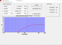
The last choice to make is the midbass driver. I'm leaning toward the NDH12-3. The Beyma 12p80FEv.2 also looks good, but it has higher Le and cost $30 more per driver. They have similar BL/MMS ratios. Only question I have is how do you build a 7.2 liter enclosure for a QTC of.7 and an F# of 177hz?
Attachments

Vb = 7.2 L
a = Vas/Vb = 9.235
Qtc = (a+1)^0.5*Qts = 0.736
Fc = (Qtc*Fs)/Qts = 176.3 Hz
------------------------
Qtc = 0.707
a = (Qtc/Qts)^2- 1 = 8.449
Vb = Vas/a = 7.87 L
------------------------
Fc = 176.3 Hz
Qts = (Qtc*Fs)/Fc = 0.22
Fs = (Fc*Qts)/Qtc = 57.35 Hz
If I did the math right, you apparently don't.

 🤐
🤐 
a = Vas/Vb = 9.235
Qtc = (a+1)^0.5*Qts = 0.736
Fc = (Qtc*Fs)/Qts = 176.3 Hz
------------------------
Qtc = 0.707
a = (Qtc/Qts)^2- 1 = 8.449
Vb = Vas/a = 7.87 L
------------------------
Fc = 176.3 Hz
Qts = (Qtc*Fs)/Fc = 0.22
Fs = (Fc*Qts)/Qtc = 57.35 Hz
If I did the math right, you apparently don't.
🤐 I've narrowed down the 12" midrange driver to cover +/- 200hz to +/- 1100hz range to the Ciare NDH 12-3 or the Beyma 12MI100. Both look very close in specs. I've run them both in AJSealed designer and have attached their sealed box alignment @ .7 QTC. I've read positive reviews of the Ciare, but I also believe the Beyma was designed more for midrange performance because of it's lower 3mm xmax. With an F3 of 177(Ciare) and 186(Beyma), can anyone see a reason to use one vs. the other running 18 or 24 db crossovers @ +/- 200hz on the low side. With digital crossovers, room, time, and response correction, I doubt I would notice the difference between the two.
Both are asking for 7 liters or .25 cu ft, but I've read of guys using .5 cu ft sealed box with the Ciare. I would appreciate any feedback on this as it's the last piece of the puzzle. Sorry GM, your math above was over my head.
Remember this is for home use at moderate or a little louder levels.
Both are asking for 7 liters or .25 cu ft, but I've read of guys using .5 cu ft sealed box with the Ciare. I would appreciate any feedback on this as it's the last piece of the puzzle. Sorry GM, your math above was over my head.
Remember this is for home use at moderate or a little louder levels.
Attachments

Hi,
You're over thinking it as I suppose you're going to use DSP with a sealed box. In home environment, these drivers will take more abuse than your ears. Make the box bigger and forget the sims...
You're over thinking it as I suppose you're going to use DSP with a sealed box. In home environment, these drivers will take more abuse than your ears. Make the box bigger and forget the sims...
How big? .5 cu ft or bigger?
Will be running Audiolense through my Lynx Hilo or maybe a motu Ultralite MKV in a 3 way active system with sealed B&C 18TBW100 up to around 200hz, and a Radian 475pb on a Pi Speakers H290C waveguide to cover 1100hz and up.
Will be running Audiolense through my Lynx Hilo or maybe a motu Ultralite MKV in a 3 way active system with sealed B&C 18TBW100 up to around 200hz, and a Radian 475pb on a Pi Speakers H290C waveguide to cover 1100hz and up.
- Home
- Loudspeakers
- Multi-Way
- 18" pro driver 3 way questions